18205
LT-2579 22142
INTRUSION • FIRE • ACCESS • NETWORKS
2500 North Partnership Boulevard
Springfield, Missouri 65803-8877
Domestic: 800.641.4282 | International: 417.831.9362
DMP.com
© 2022
Step 6: Mount the Keypad
All DMP keypad housings are designed to install on any 4” square box, 3-gang
switch box, compatible backboxes, or directly on a flat surface.
1. Ensure all cables are routed through the keypad base cut outs before fully
mounting the base to the wall.
2. Use #6 screws to secure the keypad base to the surface.
3. Place the keypad cover back onto the base and snap into place.
Step 7: Program the Panel and Keypad
For all programming instructions, see the QR code at the beginning of the document.
Step 8: Test the Keypad
For all testing instructions, see the QR code at the beginning of the document.
Step 4: Wire the Electronic Lock
The Form C relay on 7873/7873H keypads draws up to 15 mA of current and the contacts are rated for 1 Amp at 30 VDC maximum,
resistive. The wires marked NO C NC allow you to connect the device wiring to the relay for module control. Use an additional power
supply to power magnetic locks and door strikes.
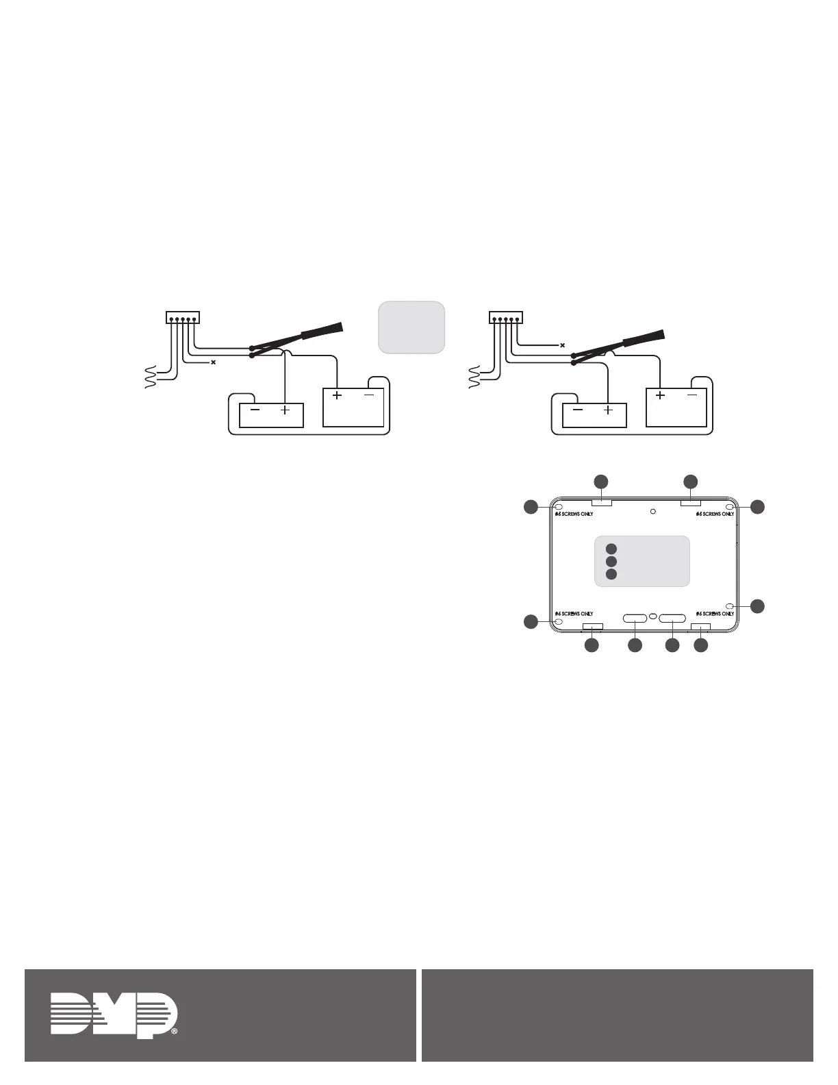
Step 5: Wire the 333 Supressor
Use the included 333 suppressor with the keypad to suppress any surges caused by energizing a magnetic lock or door strike. Install the
333 across the keypad C (common) and NO (normally open) or NC (normally closed) wires.
If the device being controlled by the relay is connected to the NO and C wires, install the suppressor on the NO and C wires. Conversely,
if the device is connected to the NC and C wires, install the 333 Suppressor on NC and C wires.
A
A
A
A
B
B
C
C C
C
A
B
Mounting holes
Wiring cutouts
C
Cover latches
Green/White – D0
White – D1
Orange – N/O
Gray – C
Violet – N/C
NC
C
NO
WHT
GRN
None
To Keypad
Magnetic Door Lock
Normally Closed
Normally Closed Normally Open
Common
Power Supply
Model 333
Supressor
NC
C
NO
WHT
GRN
None
To Keypad
Door Strike Relay
Normally Opem
Common
Power Supply
Model 333
Supressor