Do you have a question about the DMP Electronics 7800 Series and is the answer not in the manual?
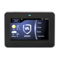
The 7800 Series Graphic Touchscreen Keypad is a sophisticated interface for security and access control systems, designed for both residential and commercial applications. This quick start guide provides essential steps for installation, wiring, and basic setup, with a comprehensive installation and programming guide available via QR code or DMP.com for detailed instructions.
The keypad serves as the primary user interface for arming/disarming security systems, viewing local weather, and accessing various system functions through an intuitive graphic touchscreen. It features an interactive arming/disarming interface, a carousel menu for navigation, and dedicated buttons for panic, chime, and reset. For enhanced security, it includes an armed/power LED and a proximity reader. The keypad also supports access control functionalities, allowing integration with electronic locks and external card readers. It is designed to be mounted on standard electrical boxes or flat surfaces, offering flexibility in installation.
| Brand | DMP Electronics |
|---|---|
| Model | 7800 Series |
| Category | Keypad |
| Language | English |