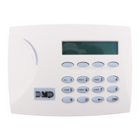
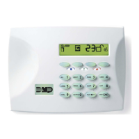
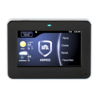
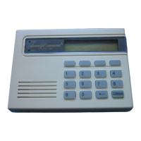
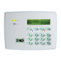
7000 Series Thinline™ and Aqualite™ Keypad
Quick Start Guide
Full Installation and Programming Guide
To view the full 7000 Series Thinline™ and Aqualite™ Keypad Installation and Programming Guide,
scan this QR code or visit DMP.com.
This quick start guide walks you through installing the keypad.
Step 1: Remove the Cover
Insert a slotted-tip screwdriver into one of the slots on the bottom of the keypad and lift the screwdriver upward. Repeat
with the other slot. Separate the cover from the base and set the cover containing the keypad components aside.
Step 2: Wire the Keypad
Use 1k Ohm EOL resistor on keypad zones 1-4.
1. Connect the harness to the keypad header.
2. Connect the red wire to panel terminal 7.
3. Connect the yellow wire to panel terminal 8.
4. Connect the green wire to panel terminal 9.
5. Connect the black wire to panel terminal 10.
Models 7060/A, 7063/A, 7160, and 7163
Supplied with a 4-wire harness for panel keypad bus
connection.
Models 7070/A, 7073/A, 7170, and 7173
Supplied with a 12-wire data bus/zone harness. Four
wires connect to the keypad bus. The remaining
eight wires are for the four zone inputs, four wires
for each zone.
Models 7073/A and 7173
Supplied with a 5-wire output/reader harness and a
12-wire data bus/zone harness.
ExternalReader/Door Strike
7073/7073A, 7173 Keypads
All Keypads
Zones 1-4
7070/7070A
7073/7073A
7170/7173 Keypads
All zones are supervised and suitable for fire applications.
Maximum zone line impendence is 100 Ohms.
Ground fault detected at 1420 Ohms or less.
Surface and Backbox
Mounting Holes
Combined 4-square
and 3-gang switch box
Mounting Holes
Surface and Backbox
Mounting Holes
Violet - Door Strike, Normally Closed
Gray - Door Strike, Common
Orange - Door Strike, Normally Open
White/Green - Reader Data 0
White - Reader Data 1
Black - Ground
Green - Receive Data
Yellow - Send Data
Red - Power
White/Yellow - Zone 4
1k Ω
White/Orange - Zone 3
1k Ω
White/Red - Zone 2
1k Ω
White/Brown - Zone 1
1k Ω
FRI 2:52 PM
A
C
B
D
F
E
G
I
H
J
L
K
V
X
W
S
U
T
P
R
Q
M
O
N
Y
Z
E
N
T
E
R
B
A
C
K
ALL RESET HOME
CHIME PERIM SLEEP
1 2 3 4
5 6 7 8
9 0
CMD
A
P
O
W
E
R
R
M
E
D
Panic Keys
Power LED
Armed LED
Proximity
Credential
Reader and
Backlit Logo
32-Character
Display
Select Keys
Command Key
Back Arrow Key