Instructions for installation, setup and operation - FP9000L-2/4/6/8
Page 10 of 16
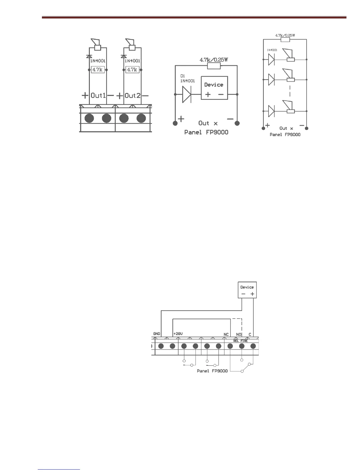
Fig. 3
If controllable outputs are not used, directly to terminals "+Outx", "-Outx" a resistor 4,7k/0,5W is
connected, otherwise the outputs will be in Fault condition.
5.3.2. Installation of the executive devices to RELAY OUTPUTS.
Used:
- Terminal "+28VDC" - positive lead of the stabilized direct voltage for external devices (light and
sound signaling devices, executive devices, etc. );
- Terminal "GND" – (negative lead for supplying the external devices);
- Terminal of the corresponding relay outputs.
Relay outputs with changeover contacts for Fault (REL Fault) and Fire (REL Fire) conditions.
- When in Fault condition of the panel, output - REL Fault, is activated immediately, regardless of
the type of fault. The output may not be disabled or delayed.
- Upon entering the panel’s condition Fire, no matter what line, output - REL FIRE be activated
immediately. The output may not be disabled or delayed.
Fig. 4
- REL Fault - terminals "REL Fault/C", "REL Fault/NO" and "REL Fault/NC" - potential free
relay contacts of the relay. In the absence of failure, there is a link between terminals "REL
Fault/C" and "REL Fault/NO", and in case of failure - between terminals "REL Fault/C" and
"REL Fault/NC".
- REL FIRE - terminals "REL FIRE/C", "REL FIRE/NO" and "REL FIRE/NC" - potential free
relay contacts of the relay. In standby mode there is a connection between terminals "REL