Instructions for installation, setup and operation - FP9000L-2/4/6/8
Page 9 of 16
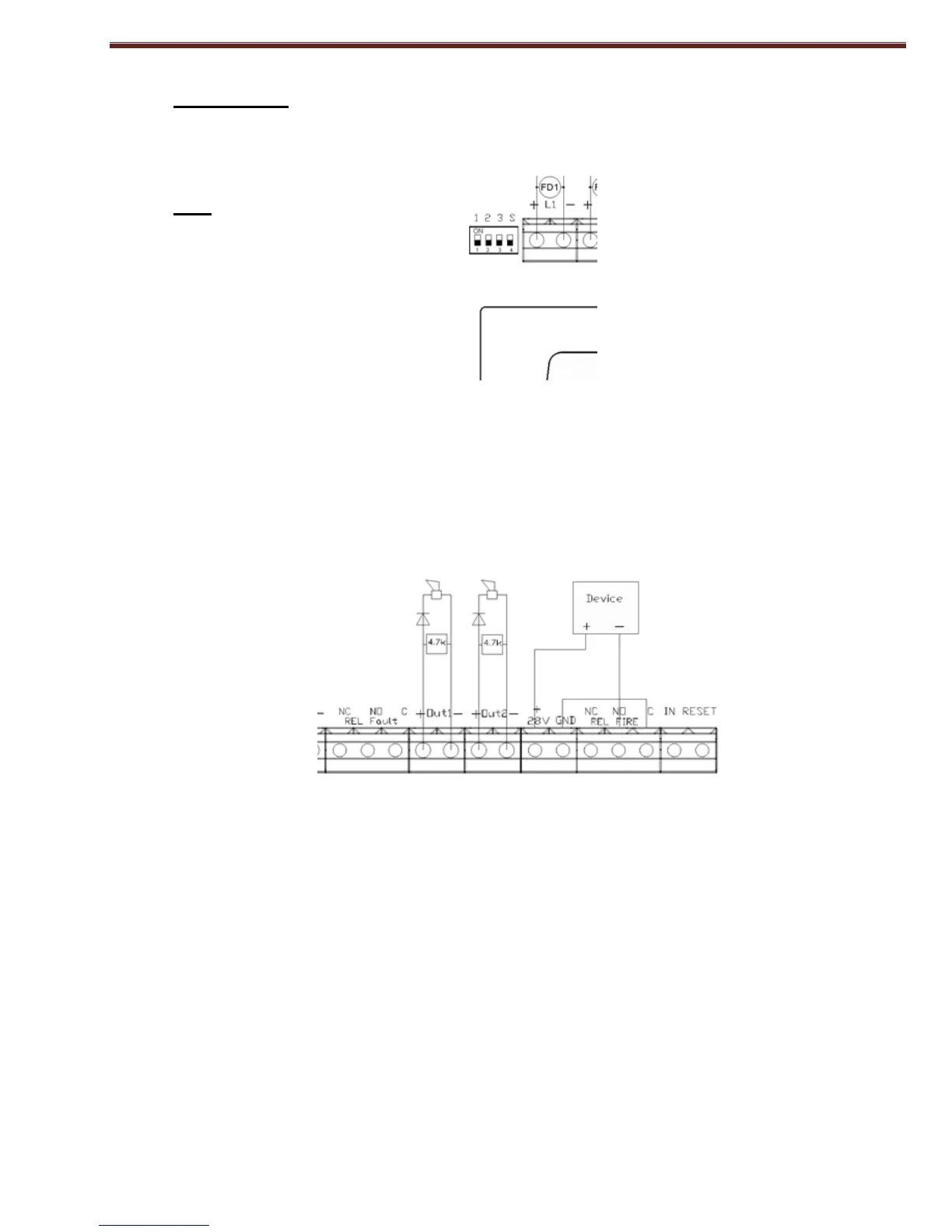
Delay Outputs
In the panel can be set to delay outputs with DIP switch on Level 3.
DIP-4
123S
000X - without delay outputs
001X - 1 minute delay
010X - 2 minute delay
011X - 3 minute delay
100X - 4 minute delay
101X - 5 minute delay
110X - 6 minute delay
111X - 7 minute delay
*Relay output for fire can be:
XXX0 - without delay - where 0 the switch 4 of DIP switch
XXX1 - with a delay - where 1 the switch 4 of DIP switch
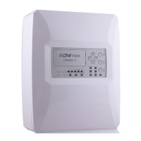
5.3. Installation of the executive devices at panel
All connections are made by means of terminals, mounted on the printed circuit board (Fig.2).
Fig. 2
Total consumption of the voltage powering the external devices (terminal "+28 VDC") and the
consumption of the controllable outputs shall not exceed 1,0 A in the heaviest mode.
5.3.1. Installation of the executive devices to the panel’s controllable outputs.
Terminals "+ Out x", "-Out x" - controllable, potential outputs, responding at Fire condition, are
used. At the end of the line a resistor 4,7k/0.5W (from the design of the panel) is mounted. It is
recommended that in series with the power supply of the corresponding device to place a diode (Fig.3).
We recommend 1N4001 diode or equivalent. The panel constantly monitors for failure (interruption or
short circuit) power line devices.