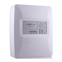
Instructions for installation, setup and operation - FP9000L-2/4/6/8
Page 5 of 16
interruption) and automatic reset;
Ability to delay controllable and general outputs for fire for a period of 0 to 7 minutes
after the registration of state Fire,with DIP switch.;
Built-in sounder in case of fire – monotonal, continuous with the possibility of exclusion;
Test mode of each (fire alarm) lines;
Ability to Disable each of the fire alarm lines;
Ability to Disable controllable outputs for fire;
Interface for communication with external devices RS485 and networking / optional /;
Possibility for GPRS communication and remote control and monitoring / optional /;
Possibility Ability to add module relay M9000R-2/4/6/8. The module expands the outputs
of the Panel.
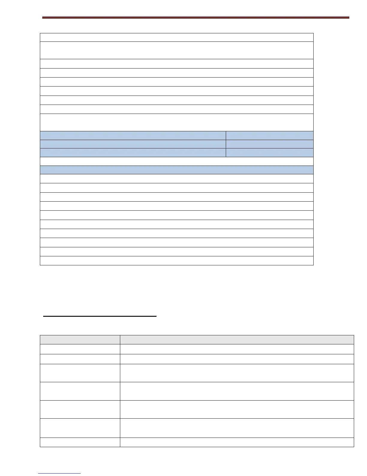
Weight without batteries
The panel meets standarts:
EN 60950-1:2006/А11:2009
3. CONTROLS AND INDICATION
LED indicators
Common indicator - flashing or constant red light in Fire condition
Flashing or continuous red light in case of a remote station Fire while working
in a network of more than one panel.
A common failure indicator. Upon failure of any type a yellow light will start
flashing
A system failure due to stoppage of the CPU. A constant yellow light will
light up. Needs to be repaired at an authorized service.
In case of fault or loss of an AC or battery power supply a steady yellow light
will light up.
When in line test condition a constant yellow light will light up.