EasyManua.ls Logo

DOF Reality H3 - User Manual

DOF Reality H3
17 pages
To Next Page IconTo Next Page
Loading...
Assembly Instructions DOF Reality H3 and P3
1
WARNING! Assembled platform will have exposed motors moving parts. Neven operate it with the
small children around or use optional protection caver.
During initial assembly don’t tighten bolts completely, rather do it at the end of the assembly.
Please First assemble the entire frame and tighten screws and bolts afterwards.
The following arrow highlights a location on the diagram or details where you need to pay extra
attention:
Please check the motors power and sensors to ensure the plug colors match. This is very
important. Never change wiring. Mismatched connector colors can damage the motors and platform
controllers.
Our platform is very lightweight and simple due to its perfect weight balance. This allows us to
use affordable motors and gearboxes. If you plan to put something besides standard wheel, pedals,
yoke, gear shifter, throttle and HOTAS you need to plan and implement it properly. Each additional,
even light element on the moving platform should be well positioned and counterbalanced (same
weight X same arm length). You can’t put even a lightweight screen/monitor on our simulator. It is
always better to consult us first, before installing any extra equipment on the platform.
Don’t put ANY accessories (joystick, pedals etc) on the platform before it is completely tested
and proven to be working as desired. After assembly, attach the seat only. Nothing extra. When you
ensure proper behavior start adding controllers one by one, doing movement tests with a person
seating in the pilot seat after each new addion to the platform weight.
If your control box don't have colored motors plugs: left motor brown plug is Motor 1, right 2
black plug, rear Motor 3 white plug
Question and Answer IconNeed help?

Do you have a question about the DOF Reality H3 and is the answer not in the manual?

DOF Reality H3 Specifications

General IconGeneral
BrandDOF Reality
ModelH3
CategoryVideo Gaming Accessories
LanguageEnglish

Summary

Lower Frame Assembly

Assembly Traction Loss Base

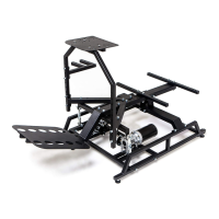
Assemble the base as per illustration, ensuring attachment hole orientation for the Traction Loss / Yaw arm.

Assemble the Lower Frame

Assemble the lower frame components according to the provided illustration, noting bolt locations.

Attach Main Motors and U-joint Mount Bracket

Secure the main motors and the U-joint mount bracket using the indicated fixing bolts.

Attach Frame to Base with Bearing

Connect the frame to the base using the bearing and secure the Traction Loss / Yaw arm rod.

Upper Frame Assembly

Attach Main Rail to Lower Frame with U-joint

Connect the main rail to the lower frame using the U-joint and securing with fixing bolts.

Attach Front Lateral Bracket

Mount the front lateral bracket, ensuring mounting holes face downwards, and attach motor pull rods.

Attach Pedals Stand and Front Motors

Install the pedals stand and the front motors, securing them with the specified fixing bolts.

Attach Seat Mount Brackets

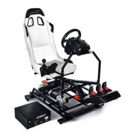
Mount the two seat support brackets and optionally attach the seat and wheel support mounts.

Attach Wheel and Shifter Stand

Mount the wheel and shifter stand to the main rail, bolting to the front lateral bracket for added rigidity.

Attach Wheel Plate and Shifter Holder

Install the wheel plate and the shifter holder bracket, securing them with the indicated fixing bolts.

Optional Mounts

Software Installation and Setup

Get SimRacingStudio (SRS) App

Download and install the SimRacingStudio (SRS) application and review the setup video.

Activate Software License

Activate your SimRacingStudio license using the provided license number.

Connect DOF Reality to SRS

Ensure your DOF Reality platform is connected and correctly identified in the SRS MOTION tab.

Install Game Plugins

Use the Auto Install button in SRS to set up necessary plugins for supported games.

Platform Balancing Procedure

Perform platform balancing by disconnecting motors and adjusting seat position for neutral balance.

VR Setup and Motion Compensation

VR Motion Compensation Methods

Explore methods for VR motion compensation, including camera placement and settings to avoid image jumping.

Troubleshooting and Maintenance

Platform Not Connected in SRS

Troubleshoot platform connection issues in SRS by checking USB connections, COM ports, and device manager.

Motor Stuck or Unresponsive

Resolve stuck or unresponsive motors by closing SRS, using SMC3Utils to reset limits, and powering on the platform.

Motor Arm Neutral Position Calibration

Recalibrate motor arm neutral position by checking coupler bolts and performing motor calibration.

General Platform Troubleshooting Steps

Address general platform issues by checking connections, using SMC3Utils, and sending diagnostic information.

SRS Antivirus Detection

Resolve SRS antivirus detection by creating an exception for the software in your antivirus settings.

Simulator Not Moving In-Game

Fix in-game movement issues by clicking Auto Install in SRS and adjusting game settings.

Simulator Stopped Working

Troubleshoot stopped simulator by checking connection loss or antivirus interference and reinstalling SRS.

Motors Make Small Adjustments

Understand that minor motor adjustments are normal due to constant power supply.

Simulator Behaves Strangely

Address strange simulator behavior by checking balance, settings, or rig weight.

Reparation Warning

Technical Specifications

Related product manuals