5-5 TAPE
SPEED
a.
Specif
ication
19
cm/sec
(l'112
iPsl
!1-5%
(2955
3
KHz
test
tape).
9.5 cm/sec
(3-3/4
iPs)
!1.5%
(2955
3
KHz
test
tape).
b. Adjustment
Adjust
the
semi-fixed
resistor
VR-901
on
the
C.P.M.
control
PC Board
Ass'Y.
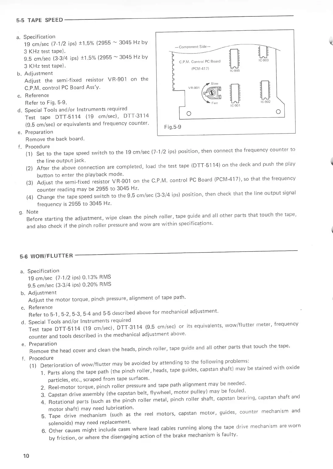
c.
Reference
Refer
to
Fig.
5-9.
d. Special
Tools
and/or
lnstruments
required
Test
tape
DTT-5114
(19
cm/sec)
,
DTT
3114
(9.5
cm/sec)
or
equivalents
and
frequency
counter'
e.
Preparation
Remove
the
back
board'
f.
Procedure
(1)
Set
to
the
tape
speed
switch
to
the
19
cm/sec
the
line
outPut
jack.
-Component
Slde-
C.P.lvl.
Control
PC
Board
(PCN1
41
7)
$-l
q_J
##
F
ig.5-9
test
tape
(DTT
51
14) on
the
deck
and
push
the
play
control
PC Board
(PCM-417),
so
that
the
frequency
-
3045
Hz
bY
-
3045
Hz bY
(-
(7-1
12
ips\
position.
then
connect
the
frequency
counter
to
(2)
After
the
above
connection
are
completed,
load
the
button
to
enter
the
PlaYback
mode'
(3)
Adjust
the
semi-fixed
resistor
VR-901
on
the
C'P'M'
counter
reading
may
be 2955
to
3045
Hz'
position,
then
check
that
the
line
output
signal
(4)
Change
the
tape
speed
switch
to
the
9'5
cm/sec
(3
3/4
ips)
frequencY
is
2955
to
3045
Hz'
q'
Note
r:..^.-^^+ ,^,i^a nraen r
de
and
all
other
parts
that
touch
the
tape,
Before
starting
the
adjustment,
wipe
clean
the
pinch roller'
tape
gul
andalsocheckifthepinchrollerpressureandwowarewithinspecifications'
5-6
WOW/FLUTTER
L
t
L
a.
Specification
19
cm/sec
(7
l12iPs]r
0'13%
RMS
9.5
cm/sec
(3-3/4
iPs)
0.20%
RMS
b.
Adjustment
Adiust
the
motor
torque,
pinch
pressure'
alignment
of
tape
path'
c.
Reference
RefertoS-1,5.2,5.3,5-4and5-5describedaboveformechanicaladiUstment.
d.
Special
Tools
and/or
lnstruments
required
TesttapeDTT-s114(1gcm/sec),DTT-3114(9.5cm/sec)oritsequivalents,wow/fluttermeter,frequency
counter
and
tools
described
in the
mechanical
adjustment
above'
e.
Preparation
Remove
the
head
cover
and
clean
the
heads,
pinch
roller,
tape
guide
and
all
other
parts
that
touch
the
tape'
f.
Procedure
(1)
Deterioration
of
wow/flutter
may
be
avoided
by
attending
to
the
following
problems:
l.Partsalongthetapepath(thepinchroller,heads,tapeguides'capstanshaft)mavbestainedwithoxide
particles,
etc., scraped
from
tape
surfaces'
2.Reel-motortorque.pinchrolIerpressureandtapepathalignmentmaybeneeded.
3.
capstan
drive
assembly
(the
capstan
belt,
flywheel.
motor
pulley) may
be
fouled'
4.
Rotational
parts
(such
as
the
pinch
roller
metal,
pinch roller
shaft,
capstan
bearing'
capstan
shaft
and
motor
shaft)
may
need
lubrication'
5.
Tape
drive
mechanism
(such
as
the
reel
motors,
capstan
motor'
guides'
counter
mechanism
and
solenoids)
maY
need
rePlacement'
6.
other
causes
might
include
cases
where
lead
cables
running
along
the
tape
drive
mechanism
are
worn
by
friction,
or
where
the
disengaging
action
of
the
brake
mechanism
is
faulty'
10
L