on the deck.
Then
enter
the
record mode
to
check frequency
response for
special
tape.
(5)
Check
that the
line
output level
of the
frequencies
between 7O0 Hz
and21 KHz is
in the range of
t3
dB
in
reference to the level
(7OO
Hz
-
21
KHz
-10
dB
12
dB) and also
that the line
output level
of the
frequencies
between
-lOO
Hz
and 30
Hz
is in the range
of
13
dB in reference
to
the
level
(7OO
Hz
-
30
Hz
-10
dB
t3
dB).
2-13
DUMMY
COIL
a. Specification
-10
dB
i3
dB
(20
KHz)
b. Adjustment
Adjust the dummy coil L-603.
c. Reference
Refer
to
Fig.6-1.
d.
Test tape, special
tools and instruments required
Blank
tape
(Scotch
#212lr
,
oscilloscope, signal
generator
and VTVM.
e. Test
point
Connect
the
VTVM
and oscilloscope
to
the line output
jacks.
f
.
Mode of
switch
(1)
Tape
speed SW-19 cm/s,
Monitor
SW
TAPE,
Equalizer
SW
NORI\1AL,
Record SW ON.
(2)
P.B. level controls MAX,
Record
level
controls-MAX.
g.
Procedure
(1)
Connect the signal
generator
to
the
line
input
jacks,
and apply a
70O Hz
signal of
-30
dB to
the
line
i n
puts.
(2)
After the above connections
are
completed, load
the
blank
tape
(Scotch
#212il
on the deck and
push
the
record
and
play
buttons
simultaneously to
enter
the record
mode.
By sweeping the
frequency from
7OO
Hz
to 20 KHz with the signal
generator,
check
that the
line output
level
is
flat
across the specified
frequencies.
Then
set the
frequency
to 20 KHz.
(3)
Set
the left record
switch OFF to
record
only in the right channel. Then record only in the
left
channel
with the left record
switch
ON and the
right
record
switch
OFF. Adjust the dummy coil
L-603
on the
REC
switch
PC
Board
(PCM-397),
so that the
difference
in
line output levels between the left and right
channel
may be within
-10
dB
r3
dB.
h. Note
Repeat
step
(3)
several time until the difference
in levels
between the
channels is within
the
specified range.
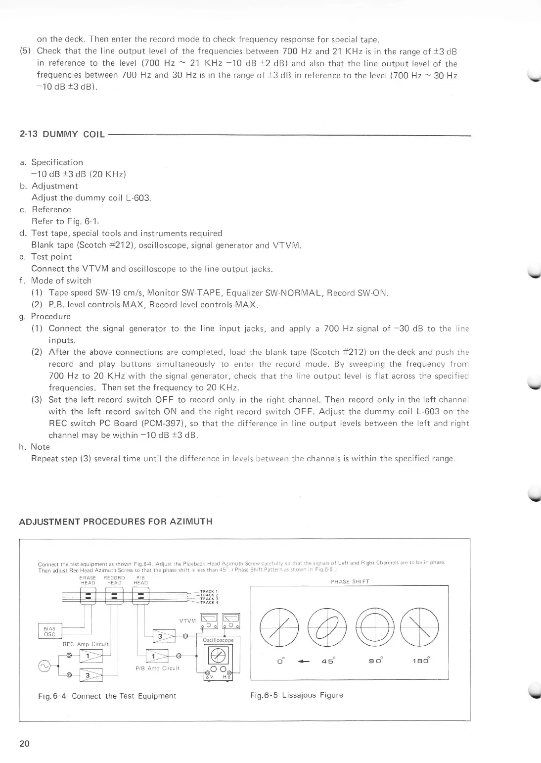
ADJUSTMENT
PROCEDURES
FOR AZIMUTH
\t
Y
V
Y
Connect the
lest equ
pment
as shown Fig.6
4.
Adjust the
P ayback
Head Azimuth Sc,erv careiu
ly
so thal
rhe sigfals of
L""11 and
R
ght
Channcls are
1o bc
in
phase
Then adlust
Rec Head
Az muth
Screw
so that the
phase
sh lt s ess thari
45
1
Phase
Shift
Pallern zs shovr'n
n F
9.6
5.)
ERASE BECCRD
P/B
HEAD HEAD
HEAD
PHASE
SHIFTPHASE SHIFT
@@@s
oo
+
as' 9oo
reo"
Fig.6-4
Connect theTest Equipment
Fig.6-5
Lissajous
Figure
20
,-