Do you have a question about the Dometic 3109228.001 and is the answer not in the manual?
Troubleshooting steps for no display on the AC/Heat Pump control. Includes reset, DC voltage, cable, and module checks.
Troubleshooting steps for improper operation with display active. Covers power, reset, configuration, wiring, and module checks.
Diagnosing issues when the fan runs but the compressor does not. Checks include start relay, capacitors, controls, and wiring.
Troubleshooting when the compressor runs but the fan does not. Focuses on fan capacitor, motor, wiring, and control modules.
Diagnosing lack of heat output when compressor and fan are operational. Checks involve reversing valve, wiring, and control modules.
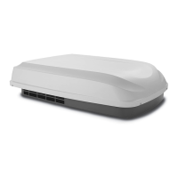
Ensuring adequate AC power supply to the unit, checking cords, fuses, breakers, and voltage at the junction box.
Details on the control cable, its specifications, proper termination with RJ-11 connectors, and avoiding extension cables.
Electrical testing of the compressor, including overload checks, continuity between terminals, and shorts to casing.
Testing compressor and fan/blower capacitors for defects like bulging, cracking, or open/shorted circuits.
Testing motor windings for continuity and shorts, and using an ammeter to check operation against model plate ratings.
Guidance on selecting remote sensor locations and testing sensor resistance against temperature charts.
Identifying and correcting electrical shorts or component failures caused by mis-wiring or loose terminals.
Diagnosis and replacement of the AC power module board, checking fuses, configuration, and voltage inputs.
Testing the reversing valve solenoid for continuity and checking refrigerant line temperature for proper operation.
Checking the PTCR device for continuity and amp draw to determine if it has replaced the start relay/capacitor.
Testing the heat strip for continuity across terminals to identify defective fuse links or heating elements.
Testing the cold (freeze) control sensor resistance against temperature charts for proper operation.
Checking the ambient sensor resistance against temperature charts for accurate outside air temperature readings.
Setting dip switches on the AC power module for component configuration and system operation.
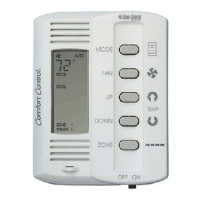
Checking the Comfort Control Center for proper DC voltage and performing a system reset for configuration changes.
Procedure for performing a system reset on the Comfort Control Center to recognize updated configuration settings.
Verifying DC voltage supply to the electronic control box and checking output voltage at the telephone wall jack.
| Cooling Capacity | 13, 500 BTU/h |
|---|---|
| Hertz | 60 Hz |
| Operating Current | 12.5 A |
| Model | 3109228.001 |
| Voltage | 115 V AC |
| Power Supply | 115 V AC |