8
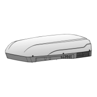
FIG. 13
A
HG
FE
D
C
B
h. Tighten mounting bolts to
correct torque specications. Overtighten-
ing could damage unit’s base pan or ceiling
template. Not enough torque will allow an in-
adequate roof seal, and could cause a leak.
Tighten all four (4) mounting bolts EVENLY
with in 4.5 to 5.6 N·m. See (FIG. 12).
F. Wiring System
1. 220 - 240 Vac Power Supply Connection
a. ELECTRICAL SHOCK HAZ-
ARD. Verify 220-240 Vac power is discon-
nected from boat. Failure to obey this warn-
ing could result in death or serious injury.
b. ELECTRICAL SHOCK HAZ-
ARD. Provide grounding in compliance with
all applicable electrical codes. Failure to
obey this warning could result in death or se-
rious injury.
The electrical installation MUST be
done by an authorized electrician. In
some areas electricians MUST be li-
censed.
You may either wire direct into the
junction box for a permanent connec-
tion or wire a molded plug into the
junction box for a plug connection.
c. If a permanent connection, connect the pow-
er supply wire to the unit at the terminal block
provided in the junction box. See (FIG. 14).
Connect RED (Active) wire to terminal (A).
Connect BLACK (Neutral) wire to terminal
(N). Connect green or bare copper wire to
terminal .
f. Hold the ceiling template up to the roof open-
ing and line up the channel in the ceiling
template with the previously installed duct
divider. See (FIG. 11).
FIG. 11
Duct Divider
Channel
g. Hold the ceiling template up to the roof open-
ing and start each mounting bolt, by hand,
through the ceiling template and up into the
unit base pan. See (FIG. 12) & (FIG. 13).
FIG. 12
Mounting Bolt
Mounting Bolt
Mounting Bolt Pattern Table See (FIG. 13)
Type Bolt Location
3341P
83341A
A, D, E & H
INSTALLATION INSTRUCTIONS