5
FIG. 3
Dimensions Are Nominal
Front
Center Line Of Unit
Roof Opening
18″
13″
39-5/8″
29-7/8″
Model
540315
540316
Keep This Air Flow Area Free Of Obstructions
FIG. 4
Dimensions Are Nominal
Model
640312
640315
Roof Opening
Front
Center Line Of Unit
9-1/2″
29″
40″
4″
4″
12″
Keep These
Air Flow
Areas
Free Of
Obstructions
Model
Number
Max Tilt
(All Directions)
Model
Number
Max Tilt
(All Directions)
457915
B57915
459516
B59516
540315
15° H540315
540316
H540316
15°
640312
640315
640316
8°
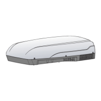
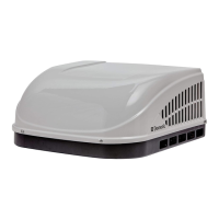
After Location Has Been Selected:
c. Check for obstructions in the area where
unit will be installed. See (FIG. 1), (FIG. 2),
(FIG. 3), (FIG. 4), (FIG. 5) & (FIG. 6).
Keep This Air Flow Area Free Of Obstructions
29-7/8″
34-7/8″
13-1/8″
18″
Front
Dimensions Are Nominal
FIG. 1
Roof Opening
Center Line Of Unit
Model
457915
459516
FIG. 2
Dimensions Are Nominal
Roof Opening
Keep This Air Flow Area Free Of Obstructions
Center Line Of Unit
Front
18″
12-7/8″
29-5/8″
27-5/8″
Model
B57915
B59516
INSTALLATION INSTRUCTIONS
 Loading...