8
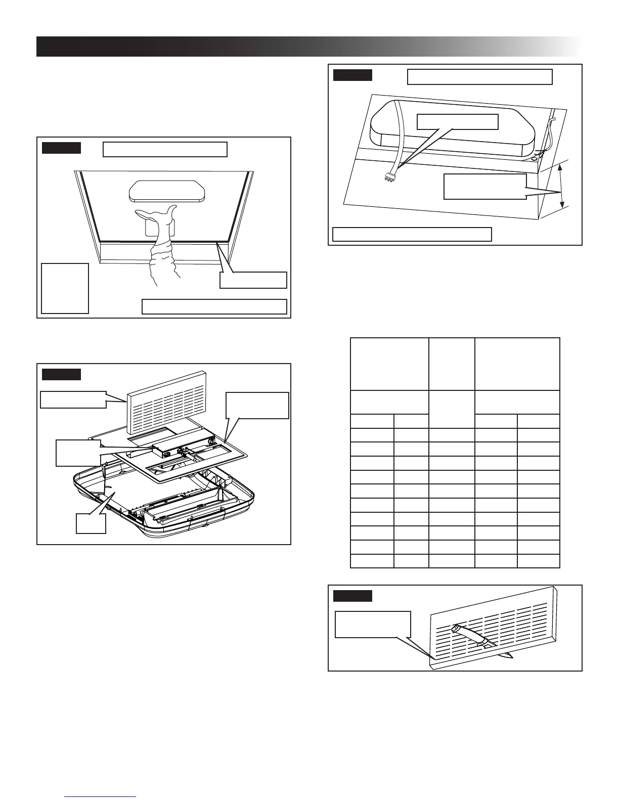
FIG. 12
Electrical Cord
Measure Ceiling
Thickness
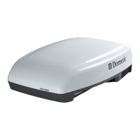
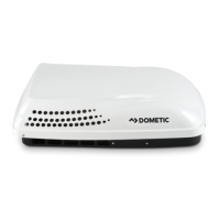
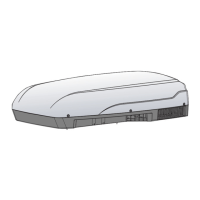
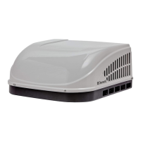
Unit May Vary In Appearance
Model H540315 H540316 Shown
F. Duct Divider Installation
1. Measure the ceiling thickness. See (FIG. 12).
2. Cut away the number of rows as indicated in the
table below. See (FIG. 13).
H540315, H540316 457915, B57915
459516, B59516
540315, 540316
640312, 640315,
640316
Ceiling
Thickness
# Of
Rows
To Cut
Ceiling
Thickness
Min. Max. Min. Max.
5.75 6.25 0 6.0 6.5
5.25 5.75 1 5.5 6.0
4.75 5.25 2 5.0 5.5
4.25 4.75 3 4.5 5.0
3.75 4.25 4 4.0 4.5
3.25 3.75 5 3.5 4.0
2.75 3.25 6 3.0 3.5
2.25 2.75 7 2.5 3.0
1.75 2.25 8 2.0 2.5
1.25 1.75 9 1.5 2.0
FIG. 13
Remove Rows
Starting Here
3. Carefully install the duct divider in the roof
opening 5-5/8″ from back of roof opening. See
(FIG. 14).
Foil back faces rear of unit.
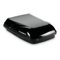
E. Installation Preparation
1. Check gasket alignment of the unit over the
roof opening and adjust if necessary. Unit may
be moved from below by slightly lifting. See
(FIG. 10).
FIG. 10
Center Unit From Below
Roof Gasket
Unit May Vary In Appearance
Model
H540315
H540316
Shown
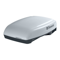
2. Remove ADB and mounting hardware from car-
ton. See (FIG. 11).
FIG. 11
Duct Divider
Ceiling
Template
ADB
Control
Box
3. All models in this manual will use a four (4) bolt
pattern for installing the ADB kit.
4. Reach up into the return air opening of the unit
and pull the unit electrical cord down for later
connection. See (FIG. 12).
INSTALLATION INSTRUCTIONS
 Loading...