9
F. Thermostat, Optional Indoor
Temperature Sensor & Thermostat
Communication Cable Installation
1. CCC 2 System
a. The previously run communication cable (4
conductor telephone cable) must be termi-
nated with two (2) RJ-11-6C4P telephone
connectors. Refer to the crimp tool manufac-
turer for crimping instructions. See (FIG. 8)
& (FIG. 9).
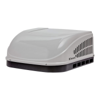
RJ-11-6C4P connectors MUST be in-
stalled as shown in (FIG. 8) & (FIG. 9).
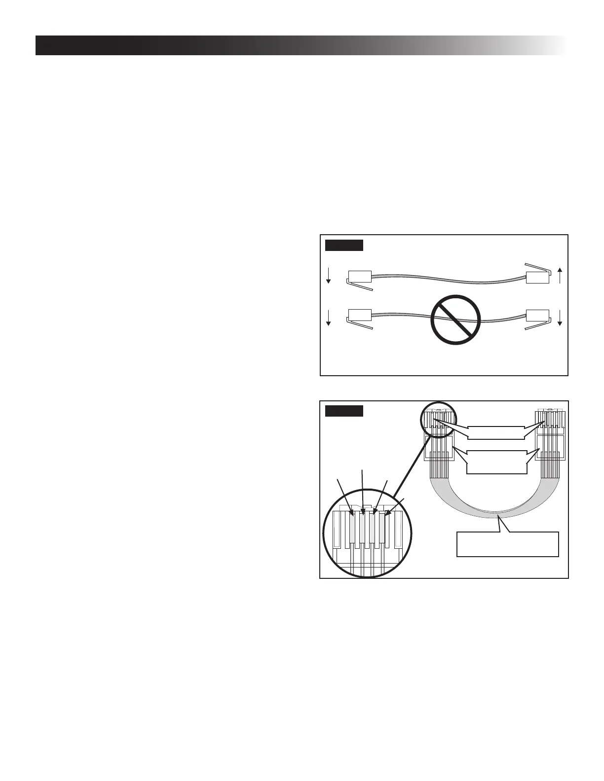
FIG. 8
FIG. 9
Flat 4-Conductor
Communication Cable
RJ-11-6C4P
Connector
Pin 1
Black
Red
Green
Yellow
b. Route the communication cable through the
2" diameter hole in the wall required for the
thermostat. See (FIG. 10).
c. Optional Indoor Temperature Sensor
I. Refer to the instructions provided with the
indoor temperature sensor for details of
installation.
a. Route an indoor temperature sensor (option-
al) from the roof opening to the indoor tem-
perature sensor location. The 2 pin connec-
tor end goes to the roof opening. See indoor
temperature sensor installation instructions
for proper sensor location.
5. If system includes a gas furnace, route two 18
gauge thermostat wires from the furnace to the
roof opening of the unit that will control it. If more
than one furnace is to be used, route the second
set of thermostat wires to the second unit. Make
sure that at least 15″ of wire extends into the
opening.
6. (CCC 2 system only) If an Energy Management
System (load shed feature) is to be used with
the control, two wires must be routed to the
roof opening of the zone to be managed. The
signal required for this function is normally an
open relay contact. When the EMS calls for the
compressor to shut off, the relay contacts should
close. Makesure that at least 15″ of theEMS
wire extends into the roof opening.
7. (CCC 2 system only) If an Automatic Generator
Start (AGS) kit will be installed, an additional 4
conductor communication cable must be routed
from the last unit to the location of the AGS kit.
Follow AGS kit instructions for installation.
E. Choosing Thermostat Location
1. CCC 2 system without an optional indoor tem-
perature sensor and LCD SZ system
a. The proper location of the thermostat is very
important to ensure that it will provide a com-
fortable RV temperature. Observe the follow-
ing rules when selecting a location.
● Locatethethermostat54″abovetheoor.
● Install the thermostat on a partition, not
on an outside wall.
● NEVER expose the thermostat to direct
heat from lamps, sun, or other heat pro-
ducing items.
● Avoid locations close to doors that lead
outside, windows, or adjoining outside
walls.
● Avoid locations close to supply registers
and the air from them.
2. CCC 2 system with an optional indoor tempera-
ture sensor in ALL zones
a. The thermostat may be mounted anywhere
in the RV that is convenient. Try to avoid
hard to reach and hard to see areas.
I. Refer to the instructions provided with the
indoor temperature sensor for details of
installation.
INSTALLATION INSTRUCTIONS
 Loading...