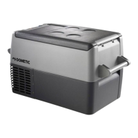
CF35, CF40, CF50 Function description
11
5.2 Operating and display elements
CF35, CF40
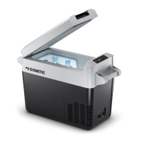
Lock for lid: fig. 2 1, page 3
CF35, CF40, CF50
Operating panel (fig. 3, page 3)
Connection sockets (fig. 4, page 4):
Item Description Explanation
1ON
OFF
Switches the cooler on or off when the button is pressed for
between one and two seconds
2 POWER Status indication
LED lights up green: Compressor is on
LED lights up orange: Compressor is off
LED flashes orange: display switched off
automatically due to low
battery voltage
3 ERROR LED flashes red: Device is switched on but not
ready for operation
4 SET Selects the input mode
– Temperature setting
– Celsius or Fahrenheit display
– Set battery monitor
5 – Display, shows the information
6 UP + Press once to increase the value
7 DOWN – Press once to decrease the value
Item Description
1 Connection socket AC voltage supply
2Fuse holder
3 Connection socket DC voltage supply
CF35-CF50-O-US.book Seite 11 Mittwoch, 10. Mai 2017 6:20 18