Installing the cooling unit Coldmachine
20
Keys for the illustrations
A
For cooling units with valve couplings
➤ Cut out a hole with a diameter of at least 30 mm (fig. c, page 7) for the cooling
lines. To do this, use a circular cutter.
No. in fig. 8,
page 5
Explanation
1 DC fan
2 Thermostat button
3 Connection plug for DC fan
4 Thermostat
5 Connection cable
No. in fig. 9,
page 6
Explanation
1 Connection cable
No. in fig. 0,
page 6
Explanation
1 Connection cable
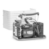
No. in
fig. i, page 9 and
fig. j, page 9
Explanation
1 Connection block
2 Compressor
3Fan
4 Switch fig. i or TEC controller fig. j
NOTICE!
Carefully insulate and seal off the wall openings after installation to
prevent moisture penetration.
DometicColdMachine50-54-55-84-85-86-94-95-96-CS-NC15_IOM_4445100001_EMEA16_20xx-xx-xx.book Page 20 Tuesday, May 4, 2021 7:24 PM