Do you have a question about the Dometic DOTRC17B and is the answer not in the manual?
Guidelines to avoid exposure to excessive microwave energy during servicing operations.
Emphasizes careful reading of the manual to avoid microwave energy exposure.
Details power consumption, output, frequency, power supply, and rated current.
Illustrates switch modes and their corresponding interlock switch states.
Advises on safe handling, avoiding specific actions like using extension cords or touching live parts.
Warns about potential microwave energy exposure from the magnetron and waveguide.
Instructions for proper unit placement, power connection, and environmental considerations.
Explains the importance of grounding for electrical safety.
Identifies and illustrates the buttons and indicators on the control panel.
Explains the function of each touch pad on the control panel for various cooking modes.
A schematic showing the interconnections of all major components in the microwave.
Provides specific wiring color codes and component symbols used in the schematic.
Illustrates the matrix circuit for the touch keyboard, mapping keys to circuit connections.
Advises on safe operation, especially regarding empty operation and aluminum foil usage.
Step-by-step guide to verify proper operation after installation or repair.
Highlights safety systems, power level selection, and multi-stage cooking capabilities.
Warns about high voltage circuits and the need for extreme care during repairs.
Details essential safety measures to prevent microwave energy leakage before and during servicing.
Lists the necessary tools and meters for performing microwave leakage tests.
Outlines the procedure for measuring microwave radiation leakage using specific equipment.
Specific instructions for measuring leakage after replacing components like the magnetron.
Procedures for checking leakage on a fully assembled oven and cavity.
Details the method for measuring the microwave oven's power output using a water load.
Step-by-step guide to safely remove the main control board assembly.
Instructions on how to properly detach an FPC connector from its socket.
Guidance on correctly reattaching an FPC connector to its terminal socket.
Detailed steps for removing the outer casing of the microwave oven.
Procedures for removing and replacing the door interlock switches.
Steps and notes for carefully removing and reinstalling the magnetron, including gasket checks.
Instructions for accessing and removing the internal stirrer fan assembly.
Steps for detaching the main oven door from the unit.
Guide on how to take apart the oven door assembly.
Procedures for correctly mounting the oven door assembly.
Steps for detaching the ventilation motor from the oven.
Instructions for replacing the humidity sensor component.
Steps to remove the turntable motor assembly.
Guide for removing the convection heater element and thermistor.
Explains the function of the door lock mechanism for preventing microwave activity.
Steps for adjusting door latches and interlock switches for proper safety.
How to inspect door latch gaps and switch alignment.
Procedures to adjust the latch board for correct switch operation.
Verifying the correct operational sequence of interlock switches when the door opens/closes.
Final check for microwave leakage after interlock system adjustments.
How to test the continuity of the primary interlock switch using an ohmmeter.
How to test the continuity of the secondary interlock switch using an ohmmeter.
How to test the continuity of the interlock monitor switch using an ohmmeter.
Procedures for measuring resistance of transformer and magnetron components.
Methods for testing capacitor and diode continuity and resistance.
Procedures for testing relays and the circulation fan motor.
Instructions for testing ventilation and damper motors.
Procedures for testing thermistor resistance and convection heater element.
Steps for measuring the resistance of the sensor component.
How to measure resistance between terminal pins of the key connector.
Identifies problems and causes for fuse blowing and necessary actions.
Troubleshooting steps for fan motor and oven lamp not turning on.
Lists symptoms indicating a potentially defective control circuit board.
Addresses common problems like oven not working, low output power, and sparks.
Lists visual display conditions that suggest a defective control circuit.
Diagnoses issues where the oven does not operate or accept input, including fuse problems.
Addresses problems with the oven not starting cooking or timer functions.
Diagnoses causes for low heat output during oven operation.
Guides through diagnosing why there is no microwave oscillation despite other functions working.
Addresses issues with the convection indicator, cooking cycle, and temperature regulation.
Illustrates the parts that make up the door assembly for model DOTRC17B.
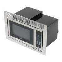
Illustrates the parts that make up the door assembly for model DOTRC17SS.
Shows the breakdown of the controller unit parts for model DOTRC17B.
Shows the breakdown of the controller unit parts for model DOTRC17SS.
Illustrates the various parts that constitute the oven cavity assembly.
Shows the individual components that make up the latch board assembly.
Diagrams of various internal components of the microwave oven.
Diagrams of additional internal components of the microwave oven.
Illustrates the parts included in the installation kit and manuals.
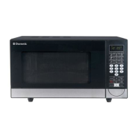
| Color | Black |
|---|---|
| Turntable | Yes |
| Voltage | 120V |
| Capacity | 1.7 cu ft |
| Wattage | 1000 Watts |
| Power Output | 1000 Watts |
| Turntable Diameter | 12.4 in |