10
Dometic Tank Monitor SystemInstallation
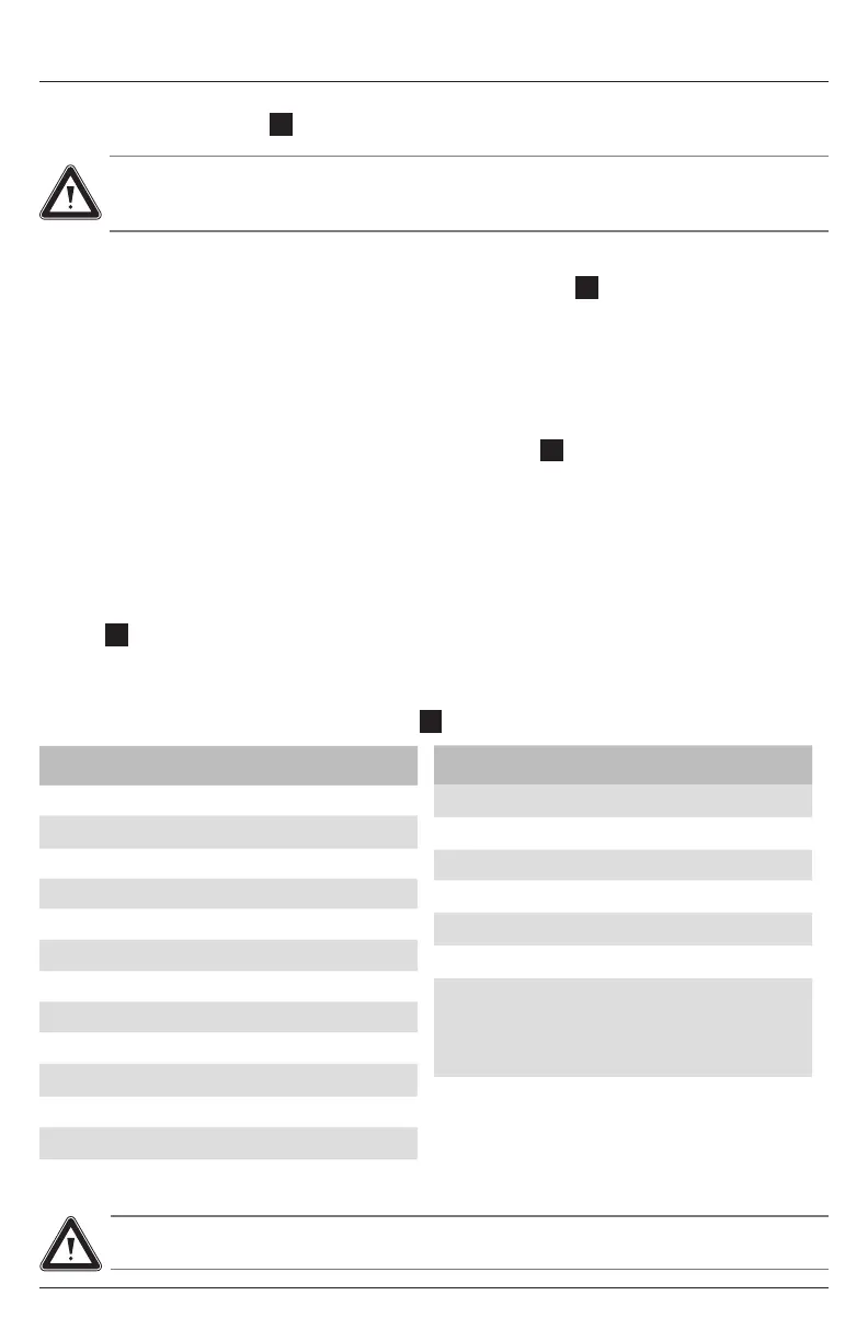
6.4 Key to DTM04 system wiring (g. 4 , page 3)
Ref. Description
A DTM04 indicator panel
B Wastewater tank
C 12 V DC
D 24 V DC
E V DC ground
F 1-amp circuit breaker or fuse
G Red
H Blue
I Black
J Green
K Yellow
L Orange
M Full level probe
4
Ref. Description
N Mid level probe
O Low/Empty level probe
P 12 or 24 V DC
Q Toilet system circuit breaker or fuse
R + V DC to electric toilet system
S + V DC to “full tank” monitor (optional)
Notes:
1. Heavy line indicates 14 gauge or larger stranded
copper wire is required.
2. Other wire can be 18 gauge stranded copper wire
or larger.
Caution!
Operator must know local regulations for emptying a holding tank.
Caution!
Do not install probe cap in fuel tank. Never install Dometic probe cap with oat switches
into a tank that contains anything other than waste water, grey water or fresh water.
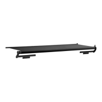
6.3 Probe Cap (g. 3 B, page 2)
1. Loosen compression nuts on adjustable probes and install probe cap into tank. Following
numbers printed on top of probe cap, slide the “1” probe (g. 3 B 4, page 3) down until the
oat touches the bottom of the tank. Tighten “1” compression nut and mark the probe tube at
the top of the nut. Do not cut the probe tube at this mark. Loosen the compression nut, slide
the probe up, and carefully cut the “1” probe tube 42 mm (1.625 inches) below the mark without
damaging the wires inside the tube. Pull the wires through the black wire cover and push the
probe down into the compression nut until the black wire cover touches the compression nut.
The recessed shoulder of the oat, or the letters “NO”, should be facing down (B 5).
2. Remove probe cap from tank and adjust the “2” probe (g. 3 B 6, page 3) for one-half full level
for black or gray water tanks. Tighten the compression nut and cut the probe tube off 10 mm
(0.375 inch) above the compression nut without damaging the wires. Slip the black wire cover
onto the top of the tube. The recessed shoulder of the oat, or the letters “NO”, should be facing
up (B 7).
3. Route 18-gauge stranded copper wires from monitor panel and DC ground source to the probe
cap. Use quick-disconnect terminals on oat switch wires to prevent twisting wires when remov-
ing the cap. With cap removed from tank, connect the wires according to the wiring diagram
(g. 4 , page 3), turn on electrical power to system, and test the oats by moving them up and
down and monitoring the DTM04 panel. Disconnect the wires and install the probe cap and O-
ring into the tank. Reconnect the wires.
3
3
3
4

 Loading...