gopowersolar.com | [page 9]
Wire Strip Length
Strip wires to a length of approximately 3/8in or 10mm, as per strip gauge.
IMPORTANT: Identify the polarity (positive and negative) on the cable used for the battery and solar module. Use
colored wires or mark the wire ends with tags indicating “Solar Positive and Negative (+ / -)”. Although the GP-SB-PWM is protected,
reverse polarity contact may damage the unit.
1.
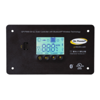
Wiring the GP-SB-PWM. Wire the GP-SB-PWM according to the wiring schematic in Section 7. Run wires from the solar panel(s) and the batteries
to the location of the GP-SB-PWM. Keep the solar panel(s) covered with an opaque material until all wiring is completed.
IMPORTANT: All wiring must be in accordance to National Electrical Code, ANSI/NFPA 70. Always use appropriate circuit protection
on any conductor attached to a battery.
2. Connect the battery wiring to the controller rst and then connect the battery wiring to the battery. Install a fuse or breaker no more than 18
inches from the battery connection.
3. Torque all terminal screws per the following:
Stranded Copper 90°C Wire
Wire Size AWG Rated Torque (in-lbs)
12 20
10 20
8 25
With battery power attached, the controller should power up and display information. Connect the solar wiring to the controller and remove the opaque
material from the solar panel(s). The negative solar connection and battery wiring must be connected directly to the controller for proper operation.
Mounting the GP-SB-PWM. Mount the GP-SB-PWM to the wall using the included four mounting screws.
IMPORTANT: You must set the battery type on the GP-SB-PWM before you begin to use the controller (follow steps in Section 8). The
default battery setting is for AGM batteries.
Your GP-SB-PWM should now be operational. If the battery power is low and solar panel(s) are producing power, your battery should begin to charge.
4.
Re-torque: After 30 days of operation, re-torque all terminal screws to ensure the wires are properly secured to the controller. Re-torque controller
connections every six (6) months of use to maintain optimal performance.
WARNING: This unit is not provided with a GFCI device. This charge controller must be used with an external GFCI device as required
by Article 690 of the National Electric Code for the installation location if required.
WARNING: When a ground fault is indicated, battery terminals and connected circuits might be ungrounded and hazardous.
INSTALLATION INSTRUCTIONS
BATTERY CHARGING PROFILE SEALED/ GEL AGM FLOODED LIFEPO4 CUSTOM
Bulk Charge Voltage Set Point 14.1V 14.4V 14.4V 14.4V
Absorption Charge Voltage (30 min / day) 14.1V 14.4V 8.16V 14.4V
Float Charge Voltage 13.7V 14.1V 8.16V 14.0V
Equalize Charge Voltage (2h / 28 days or after V < 12.1V) Disabled Disabled 14.9V Disabled 8.16V
 Loading...