EasyManua.ls Logo

Dometic PCWM-VAR - User Manual

Dometic PCWM-VAR
72 pages
Print Icon
To Next Page IconTo Next Page
Loading...
Rev: D00/2018
PCWM-VAR
CONTROLLO A INVERTER
INVERTER CONTROLS
Drive for uPC
MANUALE USO E MANUTENZIONE
USE AND MAINTENANCE MANUAL
PLDPro display ultracompatto con tasti touch a sfioramento
PLDPro ultracompact display with touch keys
PGD1 display semigrafico retroilluminato
PGD1 backlit semi-graphic display
_____________________________________________________________
Question and Answer IconNeed help?

Do you have a question about the Dometic PCWM-VAR and is the answer not in the manual?

Dometic PCWM-VAR Specifications

General IconGeneral
BrandDometic
ModelPCWM-VAR
CategoryController
LanguageEnglish

Summary

Preface and Safety Guidelines

Handbook Destination

Instructions for qualified and experienced personnel.

General Warnings and Precautions

Read all directions carefully before installing or using.

Unpacking, Inspection, and Handling

Lifting and Moving Guidelines

Guidance on how to safely lift and move the unit.

Electrical Supply and Connections

Power Supply and Grounding Requirements

Ensure proper grounding and use a differential magnetic thermal switch.

Electrical Connection Best Practices

Separate signal and power cables to avoid electromagnetic disturbance.

System Description and Features

pCO System Overview

Programmable controllers offering powerful, flexible, and easy interface.

Key Combo Drive Features

Easy control, full compressor condition monitoring, and EVD use.

System Components and Architecture

Details on microprocessors, memory, and system architecture.

User Interface and Displays

PLDPro and PGD1 Display Functions

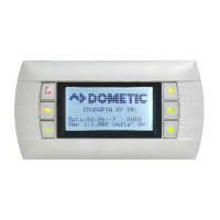
Details the functions of buttons on the PLDPro and PGD1 displays.

User Interface Navigation

Explains navigation through menus and screens.

User Settings and Parameter Navigation

How to check user parameters and navigate through programs.

Installation and Setup

Electrical Connection Checks

Checks required before connecting the unit to the power supply.

General Description and Parameter Setup

Advanced controllers requiring configuration for optimal operation.

Initial Setup Steps and Parameter Verification

Recommended to verify programmable parameters before system startup.

Compressor Operation and Management

Compressor Management and Operating Zones

Explains compressor management, operating zones, and limits.

Start-Up and Stopping Procedures

Details procedures for compressor start-up and stopping.

Compressor Alarms and Troubleshooting

Compressor Alarm Management

How the uPC controller manages compressor alarms.

Out-of-Envelope Alarms

How alarms are generated when the compressor operates outside its envelope.

Alarm Handling and Reset

Alarm management, logging, and procedures for resetting active alarms.

External Network Connectivity

BMS Communication Protocols

Supports RS485 Modbus for BMS communication.

BMS Serial Card Connection Diagram

Diagram showing the BMS serial card connection to the uPC.

Comprehensive Alarm Table

Common Faults and Solutions

Troubleshooting table for common alarms, causes, and solutions.

Specific Alarm Types and Causes

Details various alarms like Power+, sensor, temperature, and pump faults.

Maintenance Parameters and Procedures

Accessing and Setting Maintenance Parameters

Navigate to maintenance menu and enter password to adjust parameters.

Maintenance Schedule and Guidelines

Use charts as a guide for accurate maintenance based on experience.

Programmable Parameters

Second Level Service Password Access

Access to service parameters requires a password.

Authorized Personnel for Service Parameters

Only authorized personnel should adjust service parameters.

Software Update

Smart Key Software Update Procedure

Steps to connect Smart Key and update software.

Update Operation and Symbol Meanings

Explains the meaning of buttons and symbols during operation.

Related product manuals