Do you have a question about the Dometic Go Power! GP-SB-PWM-30BT and is the answer not in the manual?
| Brand | Dometic |
|---|---|
| Model | Go Power! GP-SB-PWM-30BT |
| Category | Controller |
| Language | English |
Explains the meaning and usage of various safety alert symbols presented in the document.
Highlights critical safety precautions regarding power sources and qualified personnel for installation.
Emphasizes safety when handling batteries and making wiring connections to prevent hazards.
Mandates protective gear, insulated tools, and caution when working with electricity.
Warns about reverse polarity and exceeding controller voltage/current ratings.
Stresses the need for overcurrent protection, indoor mounting, and proper ventilation.
Highlights mandatory actions like tightening connections and warnings against disassembly.
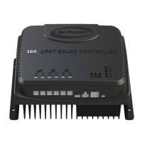
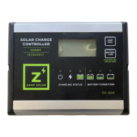
Explains the function of a solar controller and introduces the GP-SB-PWM models and their capabilities.
Lists the items included with the GP-SB-PWM solar charge controller package.
Details the compliance categories, logos, and requirements for the solar controller.
Presents detailed technical specifications for both GP-SB-PWM-10 and GP-SB-PWM-30BT models.
Explains the four-stage battery charging algorithm: Bulk, Absorption, Float, and Equalization.
Describes the Bulk charging stage, where the controller uses maximum available solar power.
Details the Absorption stage, where constant voltage charging is applied.
Explains the Float stage, where current is further reduced to maintain a lower voltage.
Describes the Equalization stage for controlled overcharging to balance battery voltage.
Provides guidelines for selecting an optimal and safe installation location for the GP-SB-PWM controller.
Discusses battery compatibility, including lead-acid and LiFePO4 types, and considerations for lithium batteries.
Lists the necessary tools and materials required for the installation of the solar charge controller.
Specifies wire stripping length and torque settings for terminal screws based on wire gauge.
Details the process of mounting the GP-SB-PWM controller to the wall using the provided screws.
Emphasizes setting the correct battery type on the controller before initial use.
Advises re-torquing terminal screws periodically for optimal performance.
Highlights GFCI requirements and warns about potential hazards from ground faults.
Illustrates the wiring connections between the solar array, battery bank, and the GP-SB-PWM controller.
Specifies the appropriate fuse or breaker size relative to the solar controller's amperage rating.
Warns of the risk of electric shock from the PV array when exposed to light.
Advises placing the controller within 3 meters of batteries for accurate temperature compensation.
Specifies the maximum installation distance for fuses or breakers from the battery connection.
Guides the user through setting up the controller for different battery types.
Step-by-step instructions for configuring the controller for lead-acid battery types.
Step-by-step instructions for configuring the controller for LiFePO4 battery types.
Explains the process of waking up a lithium battery from BMS protection using the controller.
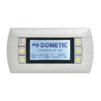
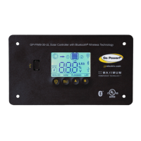
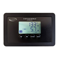
Describes the LCD screen and the function of the four mechanical buttons used for navigation.
Identifies the icons displayed on the controller's LCD screen and their meanings.
Explains the text labels used to identify different parameters on the controller's display.
Describes the numerical displays and their units of measurement for controller parameters.
Explains how the connected battery type is indicated on the controller's display.
Explains how to navigate through the controller's menus: Status, Settings, and History.
Details the status parameters displayed by the controller, including battery voltage, current, and temperature.
Shows how the display indicates when solar charging has been intentionally disabled by the user.
Lists and explains various fault and warning codes displayed by the controller.
Indicates high internal or circuit board temperatures, requiring ambient checks.
Signals reverse polarity for battery/solar or excessive solar array voltage.
Indicates failed attempts to wake a lithium battery protected by its BMS.
Describes faults related to battery overvoltage and violation of charge temperature limits.
Details the various settings available on the controller, including battery type and custom profiles.
Allows selection of battery type and temperature units for optimal charging.
Includes options to force absorption, enable/disable charging, and manage display rotation.
Provides options for soft reset and factory reset to resolve issues or restore defaults.
Resets the historical data collected by the solar controller.
Allows adjustment of voltage thresholds for overvoltage, equalization, absorption, float, re-absorb, and low voltage.
Sets the time delay before a low voltage fault is indicated after the battery voltage drops.
Determines the duration for equalization/absorption stages and the interval for equalization.
Sets the temperature compensation factor used during charging to adjust voltage based on temperature.
Displays the current firmware version programmed onto the solar controller.
Shows amp hours provided by solar panels for the current day and previous days.
Displays amp hours over 7 days, cumulative total, and controller operating days.
Explains how the controller limits current in high ambient temperatures to prevent overheating.
Guides the user through the initial pairing process between the charge controller and a mobile device.
Explains how to use the app to view status, history, and alerts from the controller.
Details how to configure battery types, temperature units, and other settings via the mobile app.
Outlines essential maintenance tasks for the solar controller, panels, wiring, and battery.
Addresses issues related to the controller's display, such as a blank screen or nighttime reading.
Covers inaccurate voltage readings, diagnosing causes like voltage drop and loose connections.
Addresses issues related to current readings, including zero current and less than expected current.
Describes array voltage testing and provides remedies for voltage reading issues.
Lists conditions and events that will void the product warranty, such as misuse or acts of God.
Provides information and contact methods for repair and return procedures for defective products.
Provides a template for accurately marking mounting hole positions for the controller.