Do you have a question about the Dometic Optimus EA1000 and is the answer not in the manual?
Explains the meaning of various safety symbols used in the manual.
Provides essential safety guidelines for operating the boat with Optimus EPS.
Lists crucial safety precautions for individuals installing the system.
Reproduces the safety decal found on the electric actuator for reference.
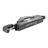
Describes the function and purpose of the electric steering actuator and SCU.
Explains how the helm converts steering wheel movement into digital messages.
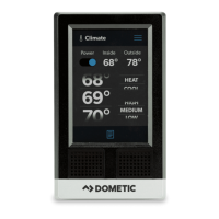
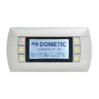
Details the functions of the CANtrak display for system status and settings.
Explains the CAN protocol and its use in Optimus EPS systems.
Describes the function of the optional Optimus 360 joystick control system.
Outlines essential steps to take before operating the boat for the first time.
Details the procedure for inspecting the steering system before each use.
Explains how to check for interference between system components.
Describes the general operation of the Optimus EPS system.
Guides the user through the initial sea trial and familiarization.
Introduces the features and purposes of the CANtrak display.
Explains how to navigate the menus and functions of the CANtrak display.
Illustrates the screen flow and options within the CANtrak display.
Describes the 'All Helms Active' screen displayed during normal operation.
Details the steering maintenance screen for calibration and move functions.
Explains how to adjust steering effort and helm turns via the Settings screen.
Discusses how steering parameters change with boat speed.
Guides on how to adjust the brightness of the CANtrak display.
Covers compatibility and basic operation with autopilot systems.
Introduces the Optimus 360 joystick control system.
Explains the basic functions and controls of the joystick.
Provides practical advice and best practices for using the joystick.
Illustrates common joystick maneuvers for docking and maneuvering.
Details the procedure for switching back from joystick to conventional controls.
Defines and categorizes different types of system faults (Danger, Warning, Caution).
Explains how the system alerts the user to faults via buzzer and display.
Outlines actions to take when a critical 'Danger' fault occurs.
Describes the 'Limp Home' mode for operating the boat with reduced functionality.
Provides a procedure for manually repositioning the steering actuator.
Explains how to handle 'Warning' faults and proceed with caution.
Gives instructions on what to do if the CANtrak display is not working.
Preparation steps and general advice before beginning installation.
Lists available actuator configurations based on engine applications.
Considerations for harness routing and slack when installing the actuator.
Step-by-step instructions for physically installing the electric actuator.
Details the procedure for installing the ground strap on the actuator.
Discusses the selection and installation of the actuator harness.
Information on choosing the correct actuator harness based on system needs.
Instructions for installing the bulkhead plate and routing the harness.
Methods for bundling and protecting the actuator harness.
Step-by-step guide for connecting the harness to the electric actuator.
Introduces the different types of electronic helm styles available.
Planning considerations for routing CAN1 harnesses to the helm.
General instructions for installing the electronic helm.
Installation details for the Front Mount Helm.
Installation details for the Sport Plus Tilt Helm.
Installation details for the Classic Tilt Helm.
Installation details for the Rear Mount Helm.
Information on available CANtrak display models and their uses.
Planning considerations for selecting and mounting the CANtrak display.
Guidelines for mounting the CANtrak display for optimal visibility.
Overview of system connections made from the actuator harness bundle.
Details on making the 12V power connections for the system.
Specific advice for connecting batteries in multi-engine configurations.
Step-by-step instructions for making 12V power connections.
Explains how to connect the CAN1 network for helms and displays.
Planning considerations for CAN1 harness lengths and extensions.
Details on routing CAN1 harnesses and securing connectors.
Explains how to connect the CAN2 network for displays and autopilots.
Planning how to build the CAN2 network with tees and terminators.
Instructions for installing CAN2 network tees and securing connections.
Details how to connect the CAN3 network for engine RPM signals.
Explains the importance and connection of the ignition-sensing wire.
Guides users through the initial system power-up and access to Dealer Menu.
Outlines the steps for performing the initial system setup.
Guides the user to select the correct system type from the options.
Instructs on selecting the appropriate steering type for the installation.
Explains how to configure the quantity of devices on the CAN network.
Details the process of 'instancing' devices to define their roles in the system.
Explains how to select the RPM source for the system.
Details the steps required for setting up the steering system.
Optional configuration for engine wedge angle adjustments.
Guides on calibrating the steering actuators for proper operation.
Explains how to adjust proportional sensitivity for helm response.
Final checks to ensure the installation is complete and correct.
Describes the optional 'Move Steering' function for diagnostics.
Provides routine maintenance schedules for owners and mechanics.
Maintenance tasks to be performed by the boat owner/operator.
Maintenance tasks to be performed by a qualified marine mechanic.
Lists common faults, their causes, and solutions.
Provides mounting templates for various electronic helm styles.
Mounting template for the Front Mount Helm.
Mounting template for the Sport Plus Tilt Helm.
Mounting template for the Classic Tilt Helm.
Mounting template for the Rear Mount Helm.
Mounting template for the Color CANtrak Display.
Mounting template for the bulkhead fitting.
Recommended maximum torque values for various bolt sizes and types.
Lists key electrical and performance specifications for the EPS system.
Details the terms and conditions of the product warranty.
Outlines the process for returning products for warranty or service.
Provides contact information for Dometic technical support.
| Model | Optimus EA1000 |
|---|---|
| Operating Temperature | -20 °C to +60 °C |
| Type | Controller |
| Category | Controller |
| Power Supply | 12V DC |