(Bulletin R55/7A) continued)
2.
3.
4.
5.
6.
7.
Apply sealing permagum (sealing tape) on
mounting plate (A; FIG.
B5).
Apply thermal mastic on the evaporator coil
(B; FIG.
B5).
Tighten screws securely to obtain proper
contact between the evaporator coil and
evaporator flange;
otherwise improper cabinet
performance may result.
Install the heater element completely back
into pocket and plug in.
Reinstall capillary tube into proper position.
a.
RMl00,
RM2600
&
RM2800 will clamp to
cooling flange. (FIG. B4)
b.
RM760, RM761
&
RM763 will extend into
retainer tube approximately 31” (FIG .
Bl)
C.
RM1300, RM1301
`
RM1303 will extend
into retainer tube approximately 36”
(FIG.
Bl)
d.
RM3600
&
RM3800 have internal thermostat
with capillary tube clamped to cooling
flange (FIG. B4)
Reconnect the burner assembly to chimney.
SEALING PERMAGUM
FIG.
B5
C. Category
#3
RC150
RC160
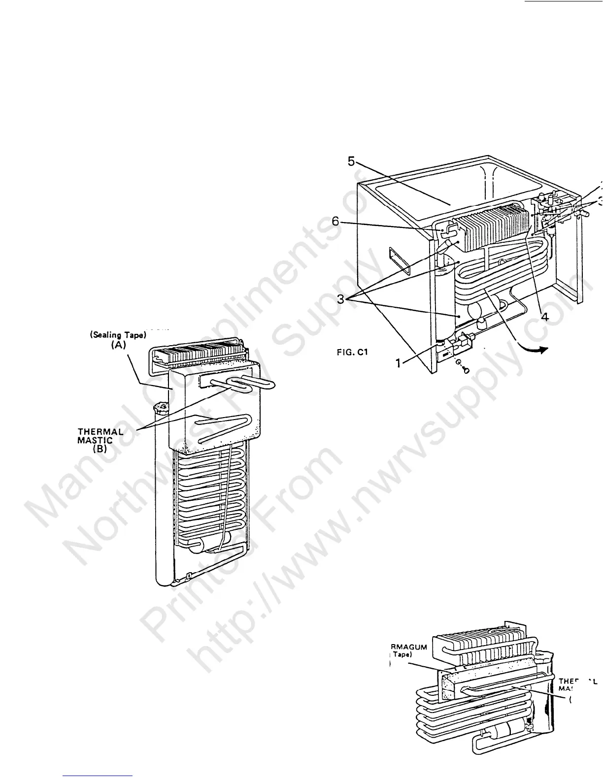
REMOVAL OF COOLING UNIT:
1. Remove screw and disconnect burner
chimney (FIG. Cl).
2. Disconnect heater wires from terminal
(FIG. Cl).
from
block
a.
Remove heaters from boiler case (FIG. Cl).
D-9-6
3.
4.
5.
6.
7.
Remove screws holding unit from rear (FIG.
Cl).
Disconnect green grounding wire (FIG. Cl).
Pull out on cooling flange to remove
fr
evaporator coil (FIG. Cl).
Pull thermostat capillary tube out gently and
move so that cooling unit will clear (FIG. Cl).
Remove cooling unit by hinging out on right
side (FIG. Cl).
INSTALL REPLACEMENT COOLING UNIT:
1.
2.
3.
4.
5.
6.
7.
Trim the Styrofoam portion of the cooling
unit if it does not go freely into the
refrigerator.
Apply sealing permagum (sealing tape) on
window insulation (A; FIG. C2).
Apply thermal mastic on the evaporator coil
(B; FIG. C2).
Tighten screws securely to obtain proper
seal; otherwise improper cabinet performance
may result.
Install the heat elements completely back
into the pocket and attach to terminal block
(FIG. Cl).
Reconnect burner assembly to chimney (FIG.
Cl).
Reinstall capillary tube into proper position
(FIG. Cl).
SEALING PE
(Sealing
(A)
FIG. C2
 Loading...