26
8.7 Cooling Unit
The cooling unit is a self-contained, hermetically sealed
set of coils where the refrigeration process takes place.
The chemicals involved in the cooling process include
hydrogen, ammonia, water and a rust inhibiting agent.
There are no repairs recommended on the cooling unit.
If it is defective, replace with a new cooling unit. To check
the cooling unit, rst verify the AC heating element is
good, proper ohms at room temperature, proper venting
and unit is level. Then place approximately one gallon of
water inside the refrigerator and place a thermometer in
one of the containers of water. Next, unplug the therm-
istor from the lower control board. This will by-pass the
thermostat control and operate for at least 12 hours. Then
check the temperature on the thermometer. It should be
at 43 degrees or lower depending on test conditions. If so,
the cooling unit is good. If the temperature of the water is
above 43 degrees, replace the cooling unit. The outside
temperature will affect the cooling capacity of the unit.
There is that rare occasion when the cooling unit will work
OK for the rst 12 hours and then start to warm up. If the
customers complaint is “works OK for 2 to 5 days and
then warms up” the unit may have an internal problem. To
test this it would be necessary to operate the cooling unit
for up to 24 to 48 hours in the test mode.
8.8 Food Storage
Proper refrigeration requires free air circulation within the
food storage compartment. Restricted air circulation within
this compartment will cause higher cabinet temperatures.
To remedy this situation, simply rearrange your foodstuffs.
It is also essential that the shelves are not covered with
paper or large storage containers. Always remember to
allow for proper air circulation. Odorous or highly avored
foods should always be stored in covered dishes, plastic
bags or wrapped in foil or waxed paper to prevent food
odors. Vegetables, lettuce, etc., should be covered to re-
tain their crispness.
NEVER PUT HOT FOOD INTO THE REFRIG-
ERATOR.
To reduce frost formation in and on the freezing compart-
ment, cover stored liquids and moist foods and do not
leave the door open longer than necessary. When the
refrigerator is heavily loaded, it takes a longer time for
refrigerator temperatures to lower, also increasing the ice
making time. A very heavy load may also cause defrost-
ing. Defrosting every 7 to 21 days would be normal, de-
pending on the humidity level.
8.9 High Humidity
High humidity may cause a small amount of condensation
to form on the frame of the refrigerator. In some cases it
can develop to such a degree that it will run off the frame.
As the humidity is reduced, the sweating will decrease.
High humidity can also be a factor in rapid formation of
frost.
9.1 Internal Wiring
Check all wires and the connectors to ensure a proper
and tight connection. Also verify the refrigerator is wired
per the wiring diagram for the model you are working on.
(See applicable wiring diagrams for your model refrigera-
tor). A loose connection can create erratic operation. Al-
ways check the wires at the DC terminal block, two wires
in and two wires out.
SECTION 9 WIRING
9.2 External Wiring
120 Volts AC Connection: The refrigerator is equipped
with a three prong (grounded) plug for protection against
shock hazards and should be plugged directly into a prop-
erly grounded three prong receptacle. DO NOT cut or re-
move the grounding prong from this plug.
12 Volt Connection : The connection is made to the ter-
minal block marked 12 volts DC. The control system is
connected to a battery/converter circuit and could draw
about 3 amps at 12 volts DC. The refrigerator must be
connected to the battery circuit with two wires of adequate
capacity to avoid voltage drop. Proper polarity is crucial
for refrigerator operation. Don’t use the chassis for the
ground circuit. No other electrical equipment or light-
ing should be connected to refrigerator circuit. A loose
connection will create erratic operation.
On three way units the DC heater will draw up to 18
AMPS and size of wires should follow installation in-
structions for the model unit you are working on.
9.3 Wiring Schematics
To view typical wiring schematics look in the Lower Circuit
board testing section 5, pages 14, 15 and 16. All units
should have a specic schematic on the rear of that unit.
To acquire the proper one always have the product num-
ber when you call or e-mail.
SECTION 10 ICE MAKER
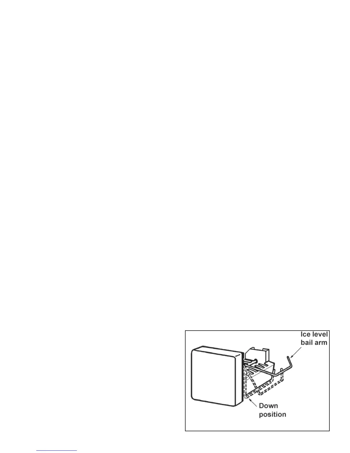
10.1 Operation
The refrigerator must be allowed to precool properly be-
fore starting the ice maker. The refrigerator has to be con-
nected to 120 volts AC before the ice maker can operate.
The water line manual shutoff valve (not part of Dometic
unit) must be open. To start making ice, move the ice level
bail arm to DOWN position.
 Loading...