21
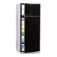
Fig. 39
4.9.2 12V (battery) connection
The machine's 12V connection cable is con-
nected (observing correct polarity) to a termi-
nal strip. The wiring for the heating element
(refer to A, B wiring diagram connections; con-
nection cable white/red) must be direct and by
the shortest possible route to the battery or
electric generator.
Cable cross sections and cable lengths :
Motorcaravan & Caravan (inside)
6 mm
²
< 6 m
10 mm
²
> 6 m
Caravan (outside)
min 2,5 mm
²
(EN1648-1
2,5mm²
Provide a 20 A fuse to protect on-board 12V
circuit.
In order to ensure that the 12V power supply is
shut off when stopping the engine (otherwise
the battery would discharge within a few
hours), perform the power supply to the hea-
ting element (cf. page 24, connection A/B in
wiring diagram) in a way to have the 12V sup-
ply only live while the vehicle ignition is swit-
ched on.
The connection C/D (interior light, electronics,
cable black / violet) must be permanently pro-
vided by a 12V DC power supply to be protec-
ted by a 2A fuse.
If the appliance is installed in a caravan
the respective leads for the 12V+ and 12V-
connections A/B and C/D must not be
connected to each other on the caravan-
side (EN 1648-1).
CAUTION!
Installation
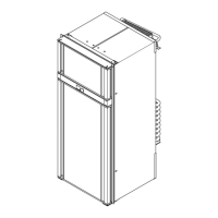
Fig. 40
4.9.3 Cable connections
Position of the control electronics :
The power supplies for electronics and hea-
ting element are connected directly at the
plug-in contacts of the electronics.
For MES and AES it is compulsory to provi-
de a permanent 12V DC supply at the termi-
nals C/D (permanent voltage supply for
functional electronics).
289 0318-40_EN_RMDT85xx-Installation_N1.qxp 02.07.2012 10:00 Seite 21
 Loading...