7
6
7
6
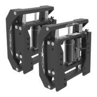
Sport Tilt Helm
STEP 1. Using the template provided (page 3) conrm that the location
of the Tilt Helm will allow unrestricted operation of the steering wheel in
ALL
tilt positions and will NOT interfere with any adjacent equipment, as well
as hardware behind the dash.
STEP 2. Tape the template to the dash and use a center punch for
locating the holes on the dash. Double check to ensure unrestricted
operation of the steering wheel in ALL tilting positions. Drill the 3”
diameter center hole and the three mounting bolt holes as shown in
the template.
STEP 3. Mount tilt plate (Item 1) to the dash using the three 1/4-20 UNC
x 2" carriage bolts (Item 2), washers (Item 3) and self-locking nuts
(Item 4). Torque nuts to 110 in-lbs (12.4 N-m).
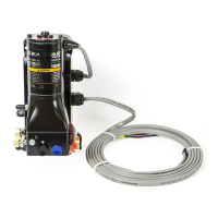
STEP 4. Install ORB ttings into rear of helm as required on page 5.
Note the ideal tting angles permitting the most efcient hose routing,
minimizing bends and avoiding features behind the dash. Make hose
connections once helm has been successfully mounted.
STEP 5. Install the remote ll brass tting, hose and clamp to helm as per
the section on Remote Fill installation. Complete the remaining remote
ll installation steps once the tilt helm has been successfully mounted.
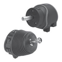
STEP 6. Mount the helm pump from behind the dash to the mounting
plate so that the four helm mounting holes align with the applicable
holes in the tilt mounting plate. Helm ll port must now be at top dead
center position. Insert the four 1/4-20 UNC x 2-1/2" hex head bolts
(Item 5) through the mounting plate to secure them to the helm pump.
Torque bolts to 110 in-lbs (12.4 N-m).
STEP 7. Attach the helm shaft to the tilt mechanism (Item 6) by lining
up the coupling slot with the helm shaft tongue and secure with the
#10-24 UNC x 7/8" cap screw (Item 7). Torque both cap screws to
20–24 in-lbs (2.5 N-m).
STEP 8. Install the two PHMS 5/16-18 UNC x 3/4" screws (Item 8), and
star washers (Item 9) to secure the tilt mechanism to the dash plate.
Torque screws to 160–180 in-lbs (19.2 N-m).
STEP 9. Install boot latch (Item 10) onto the tilt latch of tilt mechanism.
STEP 10. Position the tilt unit in the middle position and mount the
lower bezel (Item 11) to the tilt mechanism ensuring that the boot latch
(Item 10) is held into the slots provided in the lower bezel (Item 11).
Secure the bezel with the two PHMS #8-32 UNC x 1" (Item 12). Torque
screws to 16 in-lbs (1.8 N-m).
STEP 11. Install boot cover (Item 13) over lip 1 of the tilt mechanism
ange and around lip 2 of the lower bezel.
STEP 12. Grease steering shaft taper and threads with a good quality
marine grease.
STEP 13. Install woodruff key (Item 14) and wheel shaft nut (Item 15).
Tighten wheel shaft nut prior to continuing on with instructions. Torque
wheel shaft nut to 150 in-lbs (16.9 N-m), DO NOT exceed 200 in-lbs
(22.6 N-m).
STEP 14. Conrm proper function of the tilt mechanism:
• Push the tilt latch forward to unlock the tilt mechanism
•
Check ALL positions of the tilt and conrm that the latch locks in place
for each position, tilt lever will click back into the locked position.
• Ensure operation of the wheel does not interfere with the dash or
adjacent equipment.
WARNING
Use self-locking fasteners
provided ONLY; substituting
non-self locking fasteners can
result in loosening or separation
of equipment leading to loss
of steering control causing
property damage and/or
personal injury. DO NOT exceed
110 in-lbs. (12.4 N-m) torque on
helm nuts and bolts.
WARNING
NOTICE
If the helm pump shaft is difcult
to locate into the tilt mechanism
coupling, loosen the TOP screw in
the coupling (gure 5a) by no more
than 1/4 of a turn. Once connected,
ensure that this screw is tightened
to the correct torque before
installing the bezels.
WARNING
NOTICE
ONLY if the tilting function is
conrmed to function, continue to
page 10 to complete the remote
ll kit installation and page 5 for
hose connection.
 Loading...