TEC60EV Technical description
13
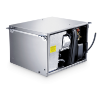
Control elements in the connection box
The connection box is located on the generator behind the cover.
Control elements in the control panel
The control panel is installed in the vehicle interior.
No. in
fig. 2,
page 3
Description
1 Main switch Switches the generator to standby or no
function.
2 Thermal protection of the
inverter
Activates if the inverter overheats (see chapter
“Display messages” on page 16)
No. in
fig. 3,
page 4
Description
1 Display Shows the status reports.
2 On/Off switch P Switches the control panel on and off if the
main switch is at “I” or “1”.
Stops the generator in emergency.
3 Grey button START/STOP Starts/stops the generator if the control panel
is switched on and the main switch is at “I” or
“1”.
4 Petrol gauge Lights up if the petrol goes into reserve.
5 Oil gauge Lights up if the oil level is too low in the
engine.
TEC60EV-O-16s.book Seite 13 Montag, 5. August 2019 12:56 12