Technical description TEC29, TEC29LPG
16
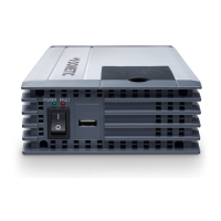
Control elements in the control panel
The control panel is located on the generator behind the cover.
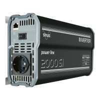
Control elements in the remote control
The remote control is installed in the vehicle interior.
No. in
fig. 2,
page 4
Description
1 Main switch Switches the generator to standby or no func-
tion.
2 TEC29 only: Cut-out switch Electromechanical protection against over-
load.
3 TEC29LPG only:
Main fuse
Triggers if the AC voltage overloads. Fuse
needs to be replaced if it has triggered.
4 TEC29LPG only:
Battery charger fuse
Triggers if the AC voltage overloads. Fuse
needs to be replaced if it has triggered.
No. in
fig. 3,
page 4
Description
1 Display Shows the status reports.
2 On/Off switch P Switches the remote control on and off if the
main switch is at “I” or “1”.
Stops the generator.
3 START button Starts the generator if the remote control is
switched on and the main switch is at “I” or
“1”.
4 TEC29 only:
Petrol gauge
Lights up if the petrol goes into reserve.
5 Oil gauge Lights up if the oil level is too low in the
engine.
TEC29-B-16s.book Seite 16 Donnerstag, 21. Juli 2016 8:09 08