INSTALLATION INSTRUCTIONS
2-18 L025317 Issue 5 July 2014
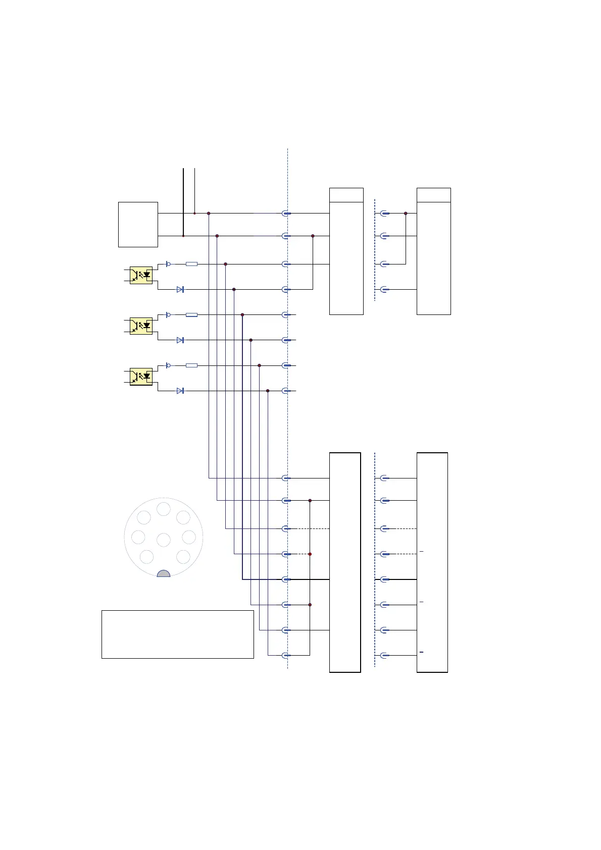
X3 Connector Schematic - Product Detector
X6 Connector Schematic - Shaft Encoder
PNP NPN
+ Supply + Supply
0V 0V
Q
Q
1
2
3
4
5
6
7
8
100
Laser - Controller Customer
(12V)
Source
24V
to the other connectors
floating
1
2
3
4
PD inputEnc A inputEnc B input
+ Supply + Supply
0V 0V
A
1
2
3
4
5
6
7
8
Input mode
B
A
B
A
B
Encoder
PNP
Differential
Input mode
Encoder
1
2
5
6
7
8
3
4
Z
ZZ
*
1
2
3
45
67
8
X3 / X6 solder side
*
*
*
X3
X6
(Standard)
In order to use the shaft encoder as a print-go
source ensure that pins 3 and 4 are connected.
In this configuration no additional
product detector should be connected.
*
Sum Load max 500mA
together with X7
2.7mA
1002.7mA
1002.7mA
 Loading...