CV01 CONTROL UNIT INSTALLATION
AND OPERATION GUIDE
1. Intended Use of the Product
DoorHan CV01 control unit is intended to be used in either wired
applications or in wireless applications to control:
electric locks,
electric operators of garage doors,
electric operators of sun blinds, rolling shutters,
indoor lighting; as well as to enable use of DoorHan consoles
with operators of other manufacturers and to automate
various devices.
2. Specifications
STEPPED CONTROL:
from remote control unit: opening — stop — closing —
stop
from switch: opening — stop — closing — stop
3. Installation
1. Remove protective packaging from the control unit. Remove
the cover of the control unit housing using a screwdriver.
2. Unscrew carefully two fixing bolts of the control unit panel
and take it out of the housing.
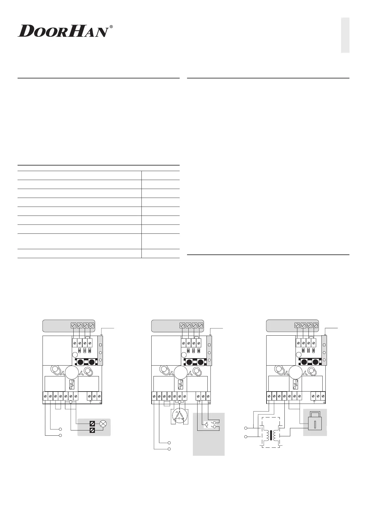
3. Connect wiring according to the diagram (Fig. 1 and 2).
4. Fix the control unit panel in the housing and place the cover
back.
When installing the device, protect it from dust and moisture.
When connecting equipment wires, if possible, use mounting
holes from the side of the terminal block (not on the top). Before
connecting, pierce the rubber plugs using an awl or a thin screw-
driver (Fig. 1) so that the diaphragm fits tightly the inserted wires.
Note:
the minimum distance from the earth — 50 sm;
the distance between neighboring control units shall be
at least 20 sm;
it is recommended to bring the receiver antenna out of the
housing for better radio signal receiving.
4. Programming
CONTROL UNIT OPERATION MODE
1. STANDBY
After the control unit power is on, it will be in standby mode
until either a command is given from the switch or from the
remote control unit or change to the programming mode is done.
Supply voltage 220 V, 50 Hz
Allowable switching current — max. 7 А
Switching voltage — max. 220±10 V
Protector operation current rating 4 А
Number of controlled electric operators 1
Dimensions 98 × 98 × 56 mm
Weight — max. 400 g
Environment temperature as per GOST 15150
from –40
to +70°С
Electrical safety class as per GOST 27570 II
ВНЕШНИЙ ПРИЕМНИК
Подключение
питания лампы
ЛАМПА НАКАЛИВАНИЯ
–12В + COM NO
–12 В+
11
12
3
P2
F1
встроенный
приемник
TR1
DoorHan
cv_
p
wr
up
dwn
P3
T
P
VR1
N L1
L1
N
220 В, 50 Гц
220
В
4
56
7
8
910
12 13 14
N
ВНЕШНИЙ ПРИEМНИК
ВЫКЛЮЧАТЕЛЬ
для управления включения
в определенную сто
рон
у
–12 В + COM NO
–12 В+
11
12
3
P2
F1
встроенный
приемник
TR1
DoorHan
cv
_
pwr
up
dwn
P3
TP
VR1
N L1
N
L1
N
220 В, 50 Гц
220 В
4
56
7
8
910
12 13 14
ВНЕШНИЙ ПРИЕМНИК
ЭЛЕКТРОЗАМОК
–12В + COM NO
–12 В+
11
12
3
P2
F1
встроенный
приемник
TR1
DoorHan
cv_
p
wr
up
dwn
P3
T
P
VR1
N L1
~220 В, 50 Гц
220
В
4
56
7
8
910
12 13 14
AC 12 V
Трансформатор
220×12, 15 W
Fig. 1 Example of lighting and external
radio control connection diagram
(to DoorHan CV01)
Fig. 3 Rolling shutter motor and external
radio control connection diagram
(to DoorHan CV01)
Fig. 4 Electric lock control
connection diagram
 Loading...