26
APPENDIX
Place for the control unit
installation
Place for the external hydraulic
power station installation
Place for the control unit
installation
Place f
or the external hydraulic
power station installation
View 1
View 1
View 1
View 2
View 2
View 2
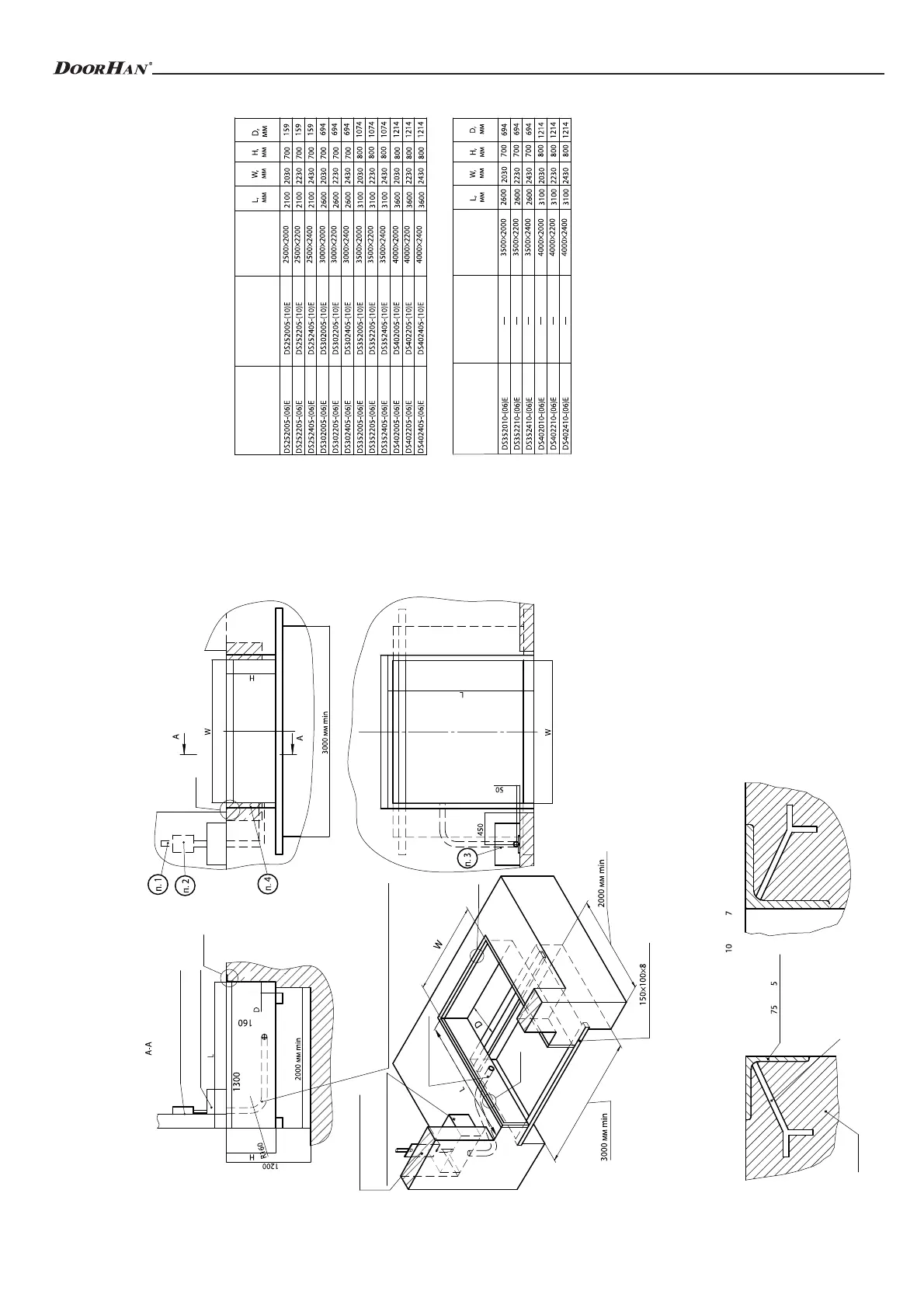
Pipe Ø80 mm for cabling from hydraulic power
station to control unit or for laying hoses from
hydraulic cylinders to external hydraulic power
station. Bend with an angle 90 °. Bending radius
is more than 160 mm
∅
Pipe 80 mm
Pipe mm
∅
Fitting 16 mm, step 300 mm
0×100×
Corner mm
×75×
Corner mm
∅
Fitting 16 mm
Concrete
Concrete
Size of the dock leveler pit (the lip 500 mm)
Size of the dock leveler pit (the lip 1000 mm)
Article of the dock
leveler series DS
with load
capacity 6 tones
Article of the dock
leveler series DS
with load
capacity 10 tones
Size of the dock
leveler
(length* x width),
mm x mm
Article of the dock
leveler series DS
with load
capacity 6 tones
Article of the dock
leveler series DS
with load
capacity 10 tones
Size of the dock
leveler
(length* x width),
mm x mm
The diagram for the pit preparation and installation of
embedded parts for the dock leveler with integrated telescopic
lip 500 mm, 2000 mm wide, 2500 mm long* and 700 mm high,
when used with vehicle with built-in lift
* Dock leveler length – from the edge of opened lip to the dock leveler cover
rotation axis.
1. 400 V (3 phases+neutral+ground) connect to the place of the control unit instal-
lation for the dock leveler.
2. It is required to provide surface of 200x300 mm for the place of the control unit
installation for the dock leveler.
3. In case of ordering the dock leveler with external hydraulic power station, it is
required to provide surface of 350x600 mm.
4. It is required to provide surface for rubber bumpers installation. See Section
“Optional Equipment”.
Diagram for the pit preparation and installation of embedded parts for the dock leveler with integrated
telescopic lip when used with vehicle with built-in lift
 Loading...