2600-267-G-6-16
Model 6500
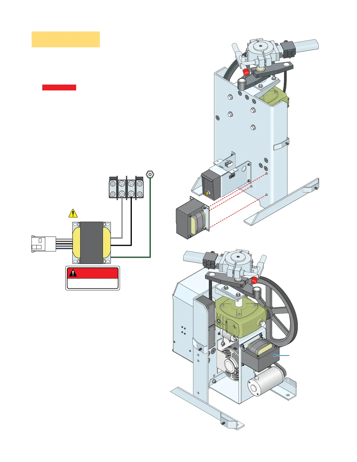
Installation for a 115 VAC 6500 primary operator ONLY.
Step 1: Bolt step-down transformer in position shown depending on the model you have using
the nuts and bolts supplied with this kit.
Step 2: Wire the step-down transformer for the desired input voltage (see first page).
Operator
MUST be
properly
grounded.
Chassis Ground
Neu Hot
Black
Green
White
115 VAC Input
115 VAC Output
115 VAC
Power Terminal
Step-Down
Transformer
Keep wires away
from moving parts.
DANGER
HIGH VOLTAGE!
Primary 6500
WITHOUT
Convenience Open
Primary 6500
WITH
Convenience Open
Operator illustrated
without electronic
box to better show
transformer
mounting position.
Reset Bo
x
Bracke
t
Dual Gate Operators Installation: When installing on
bi-parting gates, a step-down transformer and AC input
power wire is only required for the PRIMARY gate
operator. Reduce the AC input power wire run max
distance by ONE-HALF.
“Optional” Heater Installation: When installing a heater,
refer to the “high voltage AC power wire size and
distance limitations” table on the instruction sheet with
the heater kit for AC input power wire run limitations.
Important Notes:
Step-Down
Transformer
Mounting
Position
Electronic
Box
Variable Input Power
(see first page)
Double check your chosen input voltage plug BEFORE
applying power to the step-down transformer. Failure to
choose the CORRECT input voltage plug for your desired
input voltage WILL damage operator and VOID warranty.
Use 3 existing
holes to mount
step-down
transformer.

 Loading...