Do you have a question about the DoorKing 1812 PLUS and is the answer not in the manual?
Regulatory compliance details for operation in the United States.
Regulatory compliance details for operation in Canada.
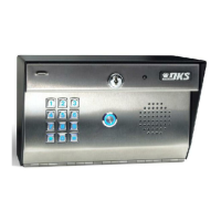
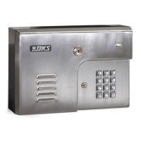
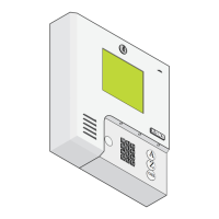
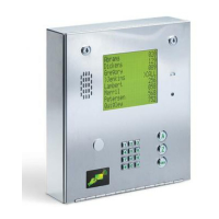
Step-by-step guide for physically mounting the 1812 Plus unit.
Instructions for installing the essential by-pass switch for system operation.
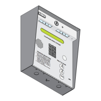
Physical dimensions and mounting hole layouts for different unit styles.
Detailed instructions on connecting the system to external telephone lines.
Procedures for correctly wiring the system's power supply.
Critical steps for protecting the system from electrical surges and proper grounding.
Specific wiring diagram for single unit telephone mode configuration.
Wiring diagram for connecting multiple units in telephone mode.
Specific wiring diagram for single unit intercom mode configuration.
Wiring diagram for connecting multiple units in intercom mode.
Detailed explanation of the function of each terminal on the main control board.
Essential first step to set the system's master code for access.
Overview of system programming methods and operational prompts.
Configuration of system settings like mode, rings, and talk time.
Programming phone numbers for directory-based dialing and access.
Programming and managing access codes for system entry.
Setting up time-based features such as schedules and time zones.
Includes procedures for restoring factory defaults and system resets.
How to adjust the output volume of the unit's speaker for optimal sound.
How to adjust microphone sensitivity for clear voice communication.
Guide for residents on granting access, handling calls, and using features.
Instructions for operating the system remotely via telephone.
Guide to diagnosing and resolving common system issues and problems.
Procedures for checking and correcting phone line polarity for proper function.
Step-by-step process for identifying and fixing audio noise issues.
Tables listing common symptoms and their corresponding possible solutions.
List and description of optional accessories available for the system.
Forms provided for recording programmed system information and settings.
| Model | 1812 PLUS |
|---|---|
| Weight | 8 lbs |
| Type | Telephone Intercom System |
| Mounting | Surface Mount |
| Compatibility | Standard analog telephone lines |
| Relays | 2 |
| Operating Voltage | 16 VAC |
| Current Draw | 500 mA |
| Relay Contact Rating | 5A @ 30 VDC |
| Wire Gauge | 18 AWG Minimum |