Do you have a question about the DoorKing 1837-084 and is the answer not in the manual?
Details for the 1835 circuit board, including wall and flush/surface mounting options.
Details for the 1833 circuit board, including flush/surface mounting options.
Detailed description of each terminal on the main connection block, including function and wiring.
Instructions for connecting the elevator control board to terminals 1-3.
Wiring and expansion board connection details for the removable 14-pin auxiliary terminal.
Description of the 6-pin terminal for PC connection and easy wiring.
Details on the non-removable Relay 0 terminal for switch input and phone line connections.
Steps for setting up the telephone entry system for PC programming, including master code and system configuration.
General programming functions accessible directly from the system keypad, such as relay strike time and talk time.
Procedures for programming names, messages, and directory information via the system keypad.
Instructions for programming phone numbers, area codes, and resident names into the system directory.
Highlights key features like resident capacity, connectivity options, security levels, and expansion capabilities.
Guides for guests and residents on how to use the system, including call procedures and entry codes.
Provides guidance on routine maintenance, cleaning, and troubleshooting common system problems.
Offers tables for logging programming information and resident details for system management.
Information regarding FCC compliance for Class A digital devices and potential interference issues.
Information regarding Canadian Department of Communications certification and user responsibilities.
Specifies the need for listed transformers and voltage/VA ratings for system power.
Confirms compliance with UL 294 and CAN/ULC-S319-05 standards by Intertek Testing Services.
Details ADA compliance requirements for mounting height and reach for door control systems.
Provides general installation steps for surface and flush mount units, including wiring and grounding.
Guidance for mounting the enclosure directly onto a wall or surface.
Instructions for mounting the enclosure onto an architectural style post.
Instructions for flush mounting the enclosure into a wall or surface.
Covers general wiring practices, power requirements, and wire run specifications.
Details power transformer requirements, wire gauge, and limitations for powering the system and devices.
Specifies wire types, conduit requirements, and maximum wire run distances for system connections.
Instructions for connecting the elevator control board to terminals 1-3.
Wiring and expansion board connection details for the removable 14-pin auxiliary terminal.
Description of the 6-pin terminal for PC connection and easy wiring.
Details on the non-removable Relay 0 terminal for switch input and phone line connections.
Wiring schematic for standard telephone entry systems without expansion boards.
Details wiring for 26, 30, and 31-Bit Wiegand card reader input to activate Relay 1.
Details wiring for 26, 30, and 31-Bit Wiegand card reader input to activate Relay 2.
Wiring instructions for powering the 14-pin auxiliary terminal and its connected devices.
Wiring instructions for powering the telephone entry system's main phone line connection.
Details board address and auxiliary terminal connections for additional expansion boards.
Specifics for connecting expansion boards to auxiliary terminals 11 through 13.
Specifics for connecting expansion boards to auxiliary terminals 7 through 9.
Details available antenna options for extending wireless communication range.
Details using DKS cellular service for voice and data communication.
Covers connecting via DKS Data over the Internet or third-party providers using network cables.
Explains connecting using a DKS IM Server Modem or a standard telephone line.
Instructions for setting up DoorKing's cellular network connection for voice and data.
Instructions for connecting the system via DoorKing's IM Server modem for voice and data transfer.
Guidance on using existing phone modems for voice and data transfer, noting limitations.
Instructions for direct PC connection using an RS-232 cable and adapter.
Guides for direct PC connection using an RS-422/USB adapter kit.
Instructions for direct PC connection using a TCP/IP converter kit.
Overview of programming methods, system relays, and important programming considerations.
Information on preparing for PC programming and the requirements for communication.
Guidance on using the system keypad for programming, including tone prompts and limitations.
Procedure for setting the required four-digit master code for system access and programming.
Enters five-digit device codes (card, transmitter, digital) and assigns them to directory codes.
Procedure for deleting individual device codes from the system.
Allows enabling or disabling the use of facility codes for system access.
Enters up to 10 facility codes (000-255) into the system memory.
Sets the strike time duration (00-99 seconds) for Relays 0, 1, and 2.
Sets the maximum conversation time for calls placed from the entry system.
Explains how to enter letters, numbers, spaces, and special characters using the system keypad.
Enters five-digit device codes (card, transmitter, digital) and assigns them to directory codes.
Procedure for deleting individual device codes from the system.
Allows enabling or disabling the use of facility codes for system access.
Enters up to 10 facility codes (000-255) into the system memory.
Enters four-digit resident entry codes and assigns them to directory codes.
Procedure for deleting specific four-digit entry codes from the system.
Sets low and high boundaries for entry codes to activate specific relays or combinations.
Configures APB operation modes: PASSIVE, ACTIVE, or TRAP.
Allows all cards to move in or out without recording an APB violation.
Resynchronizes a single card's status within the system.
Resets the facility counter used for tracking 'IN's' and 'OUTs' with APB mode.
Diagram identifying key components and adjustment points on the main circuit board.
Diagram of the 1837 LCD display board, highlighting contrast adjustment.
Diagram of the 1835/1837 LCD interface board, showing contrast and backlight cutoff.
Diagram of the 1835 LCD display boards for surface and flush mounts, showing contrast adjustment.
Explains how guests use the system to locate residents and place calls via directory code or name search.
Describes DTMF tone output from the keypad for call control and hang-up functions.
How residents grant or deny access to guests via touch-tone or rotary phones.
Explains how residents use their assigned four-digit entry codes to gain access.
Steps for remotely accessing and controlling the system via a touch-tone telephone.
Command to override and hold open all gates or doors controlled by expansion boards.
Procedure to check if system relays are in a 'hold open' mode.
Shows how to check the system's current date, time, and day of the week.
Details talk time limits for specific directory codes, reserved for management or emergency calls.
Information on sharing a phone line with multiple systems and master code requirements.
Guides for connecting to a PBX system, including programming extension numbers and line access codes.
Instructions for programming area codes in systems requiring 10-digit dialing.
Explains how the PC can operate system relays directly using Remote Account Manager Software.
A guide to diagnosing and resolving common issues encountered with the telephone entry system.
Identifies causes and solutions for buzz or noise on the phone line, including wire checks and voltage.
Solutions for speaker feedback issues, involving volume and feedback adjustments.
Addresses dial tone on speaker, door strike lock issues, and held-open operators.
Solutions for the entry system not answering calls, including ring pin installation and phone line issues.
Accessory for recessing surface mount units into walls or columns.
Kit for installing flush style units into walls or columns, includes rough-in box and trim-ring.
Accessory for surface mounting flush style units.
Optional stainless steel case replacement for the standard black steel case.
Lists phone line, low voltage, and high voltage surge suppressors for system protection.
Various mounting post options, including goose-neck and designer styles.
Boards that expand door control capabilities and add features like alarms.
Boards that provide control for elevators, including floor selection.
12-volt gel cell battery for standby power during power interruptions.
Accessory for testing telephone lines, including clips, cord, and carrying case.
Cable for direct PC programming using RS-232 communications.
Details various connection kits for PC communication: TCP/IP, VoIP, RS-422, and Cellular.
Tables to log master code, relay strike times, tone open numbers, and entry code ranges.
Table for logging area codes when the system is set to 10 area codes.
Explains how guests find residents and place calls using directory codes or name search.
Instructions for residents on how to grant or deny access to guests via phone.
Information regarding privacy options for resident names in the directory.
Explains how residents can use an access code to open the door/gate via the keypad.
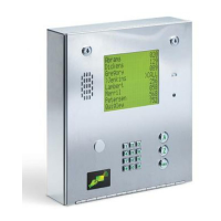
| Model | 1837-084 |
|---|---|
| Keypad | Yes |
| Housing Material | Aluminum |
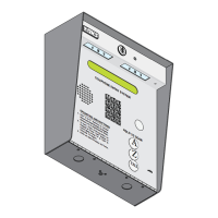
| Mounting | Surface mount |
| Compatibility | POTS (Plain Old Telephone Service) |