2358-065-L-7-16
23
34
33
32
31
30
29
28
27
26
25
24
23
22
21
14
15
16
17
18
19
20
13
12
11
10
9
8
7
6
5
4
3
2
1
ON
1
0
BOARD ADDRESS
0
9
8
7
6
5
4
3
2
1
NC
OUTPUT
RELAY
NO
NC
ALARM
RELAY
NO
NC
AUX
RELAY
NO
ENT
RESET
2358-010
RF
DATA
RF
SECURE
RF
STATUS
CODE
SENT
CODE
GOOD
CODE
BAD
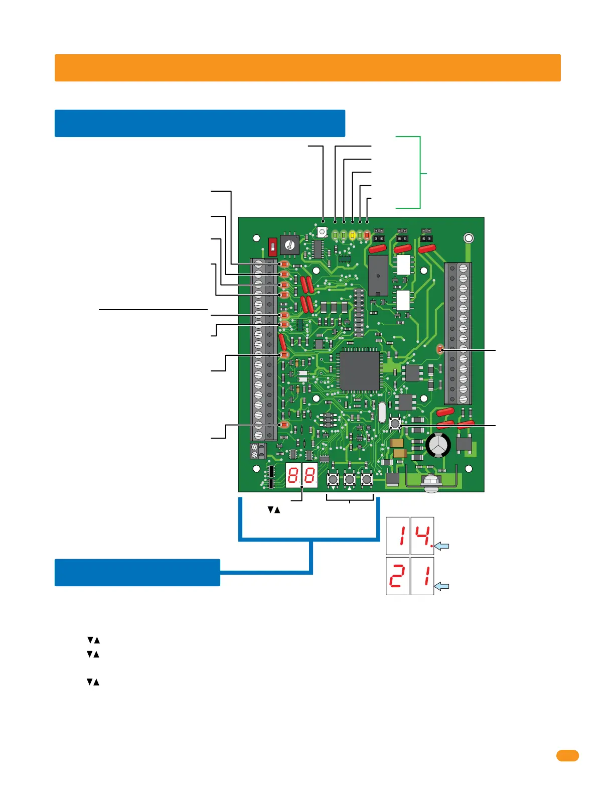
SECTION 4 - PROGRAMMING
Before beginning any programming, the tracker expansion board MUST be completely wired and the board MUST have power.
4.1 LED and Button Descriptions
RF DATA
RF STATUS
CODE SENT
CODE GOOD
CODE BAD
RESET Button
Resets board after
adjustments have
been made.
RF SECURE -
Gate Operator 1 Data Input -
Blinks red when operator data is sent.
Gate Operator 1 Data Output -
Blinks red when operator data is received.
Gate Operator 2 Data Input -
Blinks red when operator data is sent.
Gate Operator 2 Data Output -
Blinks red when operator data is received.
Wiegand Data 0 - Blinks red when
wiegand data is sent.
Wiegand Data 1 - Blinks red when
wiegand data is sent.
LED Display
Wiegand Output -
Blinks red when
wiegand data is
sent.
LED DOES NOT
function when
using wireless.
Communication Relay Input -
Blinks red when open command is received.
LED DOES NOT function when using wireless.
IMPORTANT Display Decimal Point Note
When decimal point is displayed:
Indicates you are SELECTING a
program step.
When decimal point is NOT
displayed: Indicates you are IN
a program step.
Communication “Busy” Line -
Turns ON when relay/wiegand data is
sent/received acrossed the Communication Line.
LED DOES NOT function when using wireless.
Wiegand Access Control Device
Not used when board is HARDwired.
Used with wireles communication ONLY (see wireless
tracker expansion board RF kit for more information).
These 5 LEDs are Not used when board
is HARDwired. Used with wireles
communication ONLY (see wireless
tracker expansion board RF kit for more
information).
Press buttons or
ENT button to activate
LED display.
Programming
Buttons
4.2 Programming
Follow these basic steps to perform desired programming, See programming options table for PROGRAM
STEPS on next 2 pages. EACH tracker expansion board in the system MUST be physically programmed.
1. Press arrow buttons or ENT button to ACTIVATE LED display.
2. Press arrow buttons again to SELECT desired PROGRAM STEP.
3. Press ENT button to ENTER desired PROGRAM STEP. (LED display number will blink after ENT button has been pressed).
4. Press arrow buttons to select SELECTION NUMBER for desired program step.
5. Press ENT button to program SELECTION NUMBER for desired program step. (Function has now been programmed into board).
6. Press ENT button again to exit programming OR after 10 seconds, board will automatically exit programming.
Note: Repeat these steps for all other desired programming functions for THIS tracker expansion board.
Each tracker expansion board will have to be INDIVIDUALLY programmed with desired functions.
Basic Programming Sequence on EACH Board