2358-065-L-7-16
6
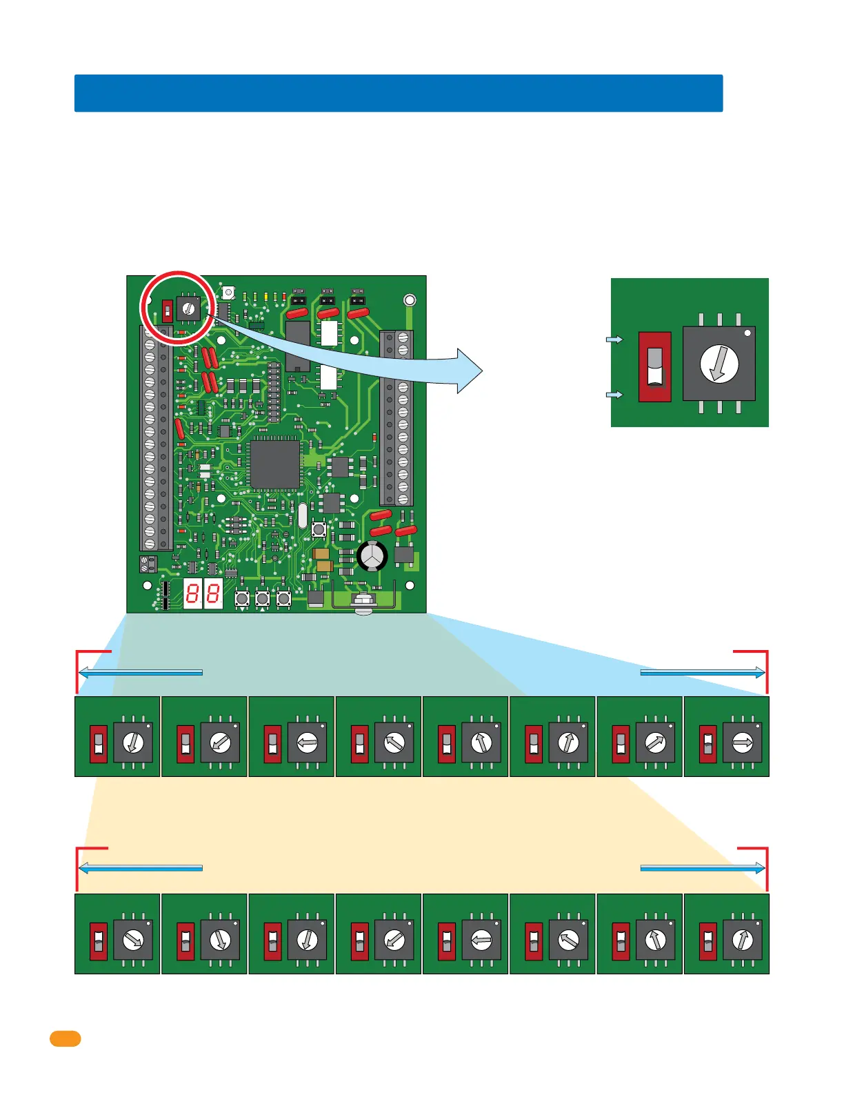
1.6 Setting Board Address (Software - System Relay)
Set dial numbers
accordingly with switch.
34
33
32
31
30
29
28
27
26
25
24
23
22
21
14
15
16
17
18
19
20
13
12
11
10
9
8
7
6
5
4
3
2
1
ON
1
0
BOARD ADDRESS
0
9
8
7
6
5
4
3
2
1
NC
OUTPUT
RELAY
NO
NC
ALARM
RELAY
NO
NC
AUX
RELAY
NO
ENT
RESET
2358-010
RF
DATA
RF
SECURE
RF
STATUS
CODE
SENT
CODE
GOOD
CODE
BAD
ON
OFF
1
0
BOARD ADDRESS
0
9
8
7
6
5
4
3
2
1
ON
OFF
1
0
BOARD ADDRESS
0
9
8
7
6
5
4
3
2
1
ON
OFF
1
0
BOARD ADDRESS
0
9
8
7
6
5
4
3
2
1
ON
OFF
1
0
BOARD ADDRESS
0
9
8
7
6
5
4
3
2
1
ON
OFF
1
0
BOARD ADDRESS
0
9
8
7
6
5
4
3
2
1
ON
OFF
1
0
BOARD ADDRESS
0
9
8
7
6
5
4
3
2
1
ON
OFF
1
0
BOARD ADDRESS
0
9
8
7
6
5
4
3
2
1
ON
OFF
1
0
BOARD ADDRESS
0
9
8
7
6
5
4
3
2
1
ON
OFF
1
0
BOARD ADDRESS
0
9
8
7
6
5
4
3
2
1
ON
OFF
1
0
BOARD ADDRESS
0
9
8
7
6
5
4
3
2
1
ON
OFF
1
0
BOARD ADDRESS
0
9
8
7
6
5
4
3
2
1
ON
OFF
1
0
BOARD ADDRESS
0
9
8
7
6
5
4
3
2
1
ON
OFF
1
0
BOARD ADDRESS
0
9
8
7
6
5
4
3
2
1
ON
OFF
1
0
BOARD ADDRESS
0
9
8
7
6
5
4
3
2
1
ON
OFF
1
0
BOARD ADDRESS
0
9
8
7
6
5
4
3
2
1
ON
OFF
1
0
BOARD ADDRESS
0
9
8
7
6
5
4
3
2
1
ON
OFF
1
0
BOARD ADDRESS
0
9
8
7
6
5
4
3
2
1
Note: Start at board address 3, the software reserves board address (system relay) 0, 1 and 2 for the access control system ONLY.
Note: Board Addresses 0, 1, 2 & 19 will not generate a wiegand signal.
Example: The switch is OFF and
the dial is set to 3, so the Board
Address is 3. The software uses
the board address as the System
Relay, this means the System
Relay for this board is 3. See
below for all board settings.
Switch
Maximum HARD wire run between tracker expansion boards (up to 12 boards) is 4000 feet TOTAL,
see section 2 for more information about HARDwiring limitations.
Dial Numbers
Maximum HARD wire run between tracker expansion boards (up to 12 boards) is 4000 feet TOTAL,
see section 2 for more information about HARDwiring limitations.
IMPORTANT: DO NOT
set the board address
to 0, 1, 2 or 19.
Switch MUST be ON (1) for
board addresses 10 thru 18.
(Dial number +10).
Switch MUST be OFF (0) for
board addresses 3 thru 9.
(Dial number only).
Board Address 3
System Relay 3
Board Address 4
System Relay 4
Board Address 5
System Relay 5
Board Address 6
System Relay 6
Board Address 7
System Relay 7
Board Address 8
System Relay 8
Board Address 9
System Relay 9
Board Address 10
System Relay 10
Board Address 11
System Relay 11
Board Address 12
System Relay 12
Board Address 13
System Relay 13
Board Address 14
System Relay 14
Board Address 15
System Relay 15
Board Address 16
System Relay 16
Board Address 17
System Relay 17
Board Address 18
System Relay 18
Board addresses 11 thru 18 MUST connect to Relay 1/Wiegand 1 on the access control system
Board addresses 3 thru 10 MUST connect to Relay 2/Wiegand 2 on the access control system
When using tracker expansion boards connected to a single access control system, the board addresses on EACH tracker expansion board
should be set so that the Remote Account Manager for Windows (V 5.0 or higher only) software can identify each tracker expansion
board. The software reserves board address 0, 1 and 2 for the access control system. Tracker expansion board address starts with relay
address 3 (see below). IMPORTANT: The software uses the board address number for the System Relay number.
“Zone” Addresses: Board addresses can be set the same (functions as “zones”), but the system’s “tracking” capability will NOT be able to
distinguish SPECIFIC access point activity. Two or more boards with the same board address will be tracked and logged as “zone number”
but not a specific location for that activity. For example, if you have 4 card readers in different locations in a building, and all have the same
board addresses, the software would track that a card reader in the “zone number” was used, but not which specific location it was used.
Zones can be used for a restricted area with multiple entrances inside the complex such as a pool area/tennis courts or community center.
Zones are not recommended if detailed tracker activity reports are required.