DL06K Interim Tire-4 Diesel Engine Technical Information
39
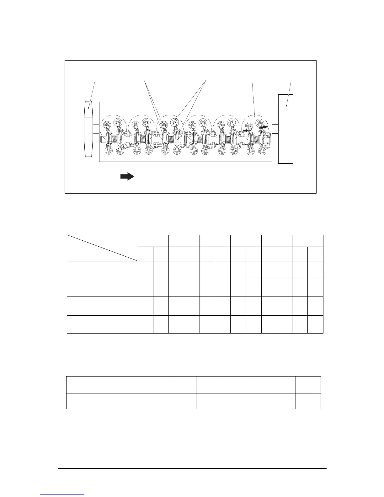
z The cylinder that the cooling fan is assembled is the cylinder number 1.
z Adjusting of valves (Type 1)
Cylinder no.
Valve adjusting
1 2 3 4 5 6
Exhaust Intake Exhaust
Intake
Exhaust Intake Exhaust Intake Exhaust Intake Exhaust Intake
#1 cylinder top dead center
(#6 cylinder valve overlap)
A A A A A
180° rotation
(#5 cylinder top dead
center)
B
360° rotation
#5 cylinder top dead center
(#1 cylinder valve overlap)
C C C C C
540° rotation
(#2 cylinder top dead center)
D
z Adjusting of valves (Type 2)
Adjusting of the valve overlapping on cylinder is done as follow.
When each cylinder is valve overlap
(Firing cylinder no. order)
1 5 3 6 2 4
Valve adjusting cylinder No 6 2 4 1 5 3
EK4OM014
123456
Cooling fan Exhaust valve
Intake valve Cylinder no.
Flywheel
Valve clearance adjusting position