Do you have a question about the Doosan DL250-5 and is the answer not in the manual?
Indicates an imminently hazardous situation leading to serious injury or death if not avoided.
Indicates a potentially hazardous situation leading to serious injury or death if not avoided.
Essential PPE includes hard hats, safety shoes, glasses, masks, gloves, and ear protection for safety.
Always wear appropriate footwear, face the machine, clean surfaces, and use handrails.
Always fasten your safety seat belt to prevent serious injury or death.
Avoid lift arm control lever displacement or part failure; never stand under a lifted arm.
Check fluid levels, filters, work tools, tyres, leaks, and system operations.
Identifies key controls like steering wheel, pedals, FNR lever, and dashboard.
Explains speedometer, warning lights, parking brake, and other dashboard indicators.
Details engine RPM, transmission, fuel level, AdBlue level, and warning lights.
Describes selection, exit, confirmation, and special function touches on the front console.
Details DL420CVT-5 touch pad functions like bucket return to dig and lift arm suspension.
Explains the transmission lever for forward, neutral, reverse, and range selection.
Identifies elements like armrest, FNR control, starting key, and parking brake.
Identifies joystick buttons for horn, FNR, kick-down, and hydraulic functions.
Illustrates joystick movements for lift, crowd, dump, and return to dig functions.
Steps to engage and operate Forward/Neutral/Reverse using the joystick.
Explains functions like arm float, lift, dump, and bucket return to dig.
Covers activating electric steering and adjusting the control unit position.
Steps for starting the machine in very cold temperatures, including parking brake ON.
Operation in Limited Drive Mode for cold temperatures, restricting to first gear and neutral shifts.
| Brand | Doosan |
|---|---|
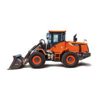
| Model | DL250-5 |
| Category | Front End Loaders |
| Language | English |