4. Regular inspection
62
Cylinder block/head
Valve Clearance
Adjust the valve clearance.
• When disassembling the engine or cylinder head.
• When there is excessive noise in the valve connection.
• When the engine runs abnormally even if the fuel injec-
tion system is normal.
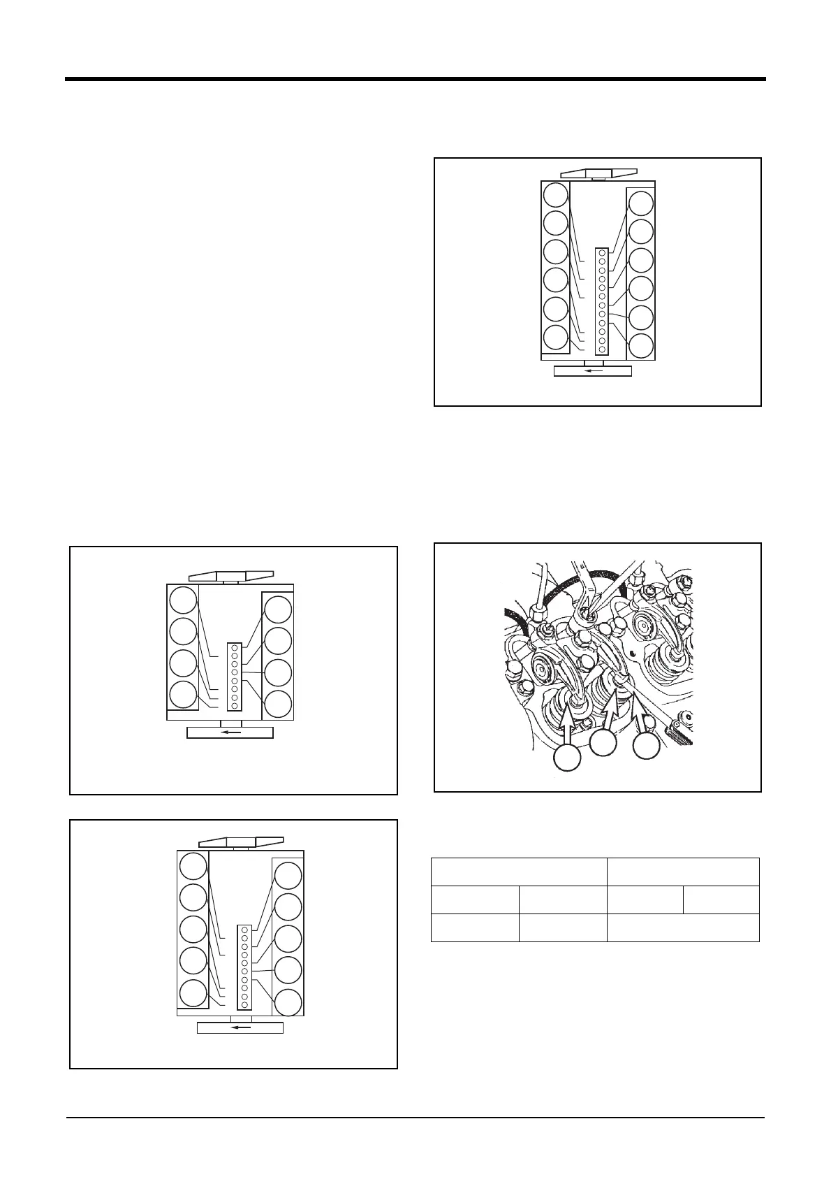
Adjusting the Valve Clearance
Method 1
1) Rotate the crankshaft so that #1. cylinder may be posi-
tioned at the compression TDC (Top Dead Center).
Note) #1. Cylinder is located at the side where cooling water
pump was installed.
Note) In case of 8/12 cylinder engine, #6. cylinder is posi-
tioned at the valve overlap when #1. cylinder is posi-
tioned at the compression TDC (Top Dead Center).
Note) In case of 10 cylinder engine, #7. cylinder is positioned
at the valve overlap when #1. cylinder is positioned at
the compression TDC (Top Dead center).
DV2213042A
DV2213213A
DV2213043A
2) Loosen the lock nut of the #1. cylinder rocker arm.
3) Push the feeler gauge between a rocker arm and a valve
stem.
4) Adjust the clearance screw respectively and then tighten
with the lock nut.
dv2213041a
5) As for the valve clearance, adjust it when in cold, as
follows.
6) Rotate the crankshaft. When a cylinder reaches the
compression TDC (Top Dead Center), adjust the valve
clearance of the cylinder.
7) When a cylinder valve overlap, adjust the valve clearance
cylinder of the compression TDC (Top Dead Center), as
follow.
5
6
7
8
1
2
3
4
8
7
6
5
4
3
2
1
8 Cylinder engine
6
7
8
9
10
1
2
3
4
5
10
9
8
7
6
5
4
3
2
1
10 Cylinder engine
Specified value Measurement tolerance
In. valve Ex. valve In. valve Ex. valve
0.25 mm 0.35 mm ±0.05 mm
7
8
9
10
11
12
1
2
3
4
5
6
12
11
10
9
8
7
6
5
4
3
2
1
12 Cylinder engine