G424F(FE) Service Manual Chapter 3. Engine Mechanical System 75
8. Camshaft cover-to-cylinder block breather hose,
with special clamp pliers.
9. Ground cable from the camshaft case lower rear
area with a Torx E12 wrench.
10. Harness support and hose support from the
intake manifold side, with a 13-mm combination
wrench.
11. Timing belt rear cover; see “Timing Belt Rear
Cover – Removal”, in this section.
12. Generator support-to-intake manifold attaching
bolt, with a 6-mm Allen wrench.
13. Air conditioning upper support, with a Torx E12
wrench to loosen the attaching bolt, support-to-
manifold stud upper nuts, with a 15-mm socket
wrench and handle.
14. Drain the coolant, loosening the radiator lower
hose.
15. Radiator-to-thermostat upper hose, loosening
the thermostat clamp with a 6-mm socket wrench
and handle.
16. Hot air hose from cab to pipe, with special clamp
pliers.
17. Heat sink attaching bolts, with a 10-mm socket
wrench and handle.
18. Exhaust heat sink.
19. Exhaust pipe-to-exhaust manifold attaching bolts,
with a 13-mm socket wrench and handle.
20. Hot air pipe attaching bolt, from the cylinder
block, with a 13-mm socket wrench, extension
and handle.
21. Hot air pipe hose clamp-to-radiator lower hose
attaching bolt, with a 7-mm socket wrench and
handle.
22. Hot air pipe hose.
23. Thermostat pipe; see “Thermostat Pipe –
Removal”, in this Section.
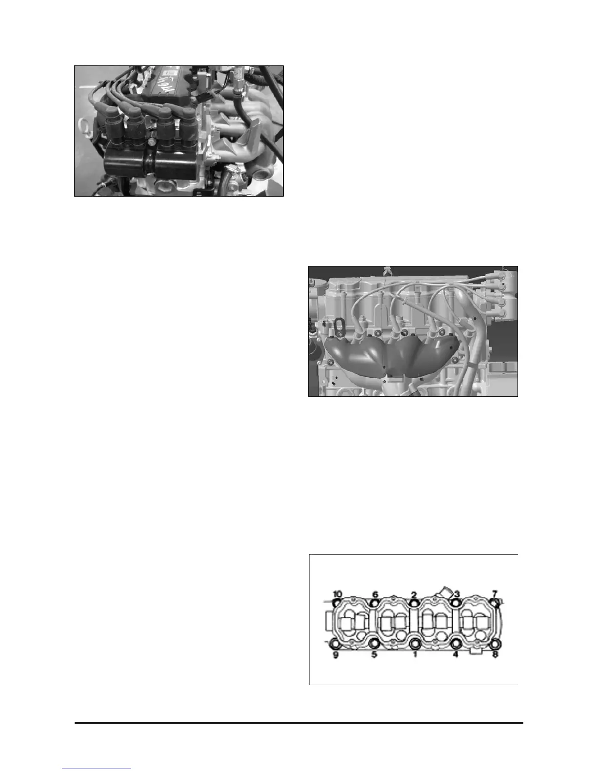
24. Cylinder head-to-cylinder block bolts, with a Torx
T-55 wrench, extension and handle; for the front
bolts, use a 19-mm socket wrench, extension
and handle.
Obs.: Loosen the bolts in the sequence shown,
loosening 1/4 of a turn, 1/2 turn and next removing
them.
25. Camshaft case.
26. Rocker arms, linkages and valve lifters, without
mixing them, so that they may be assembled in
the same position.
27. Cylinder head with intake and exhaust manifolds,
which are attached on the same, and the cylinder
head gasket.
Obs.: The cylinder head should be removed due to
the replacement of the gasket by a new one.