G424F(FE) Service Manual Chapter 3. Engine Mechanical System 76
28. Attach the camshaft case on a vise.
Obs.: Use protecting jaws in the vise.
29. Camshaft rear cover attaching bolt, with a 10-
mm wrench combination wrench.
30. Camshaft case rear cover and gasket.
31. Camshaft lock-to-case attaching bolts, with a 5-
mm Allen wrench.
32. Lock; for that, displace the camshaft a little to
the outside.
33. Camshaft, by its rear side.
Installation
Install or connect
1. Camshaft in the case.
Important
• Despite the camshaft end being chamfered, take
care not to damage the seal.
• When installing a new camshaft, drain the
engine oil, apply zinc ditiophosphate additive in
the camshaft lobes and rocker arms and add the
remaining additive to the new engine oil.
2. Camshaft lock and attaching bolt, without
tightening.
3. With a 5-mm Allen wrench and torque wrench,
give the final tightening.
Tighten
• Bolts: 4 – 10 N·m
4. Camshaft case rear cover, with a new gasket and
attaching bolts, without tightening.
5. With a 10-mm socket wrench and torque wrench,
give the final tightening.
Tighten
• Bolts: 6 – 10 N·m
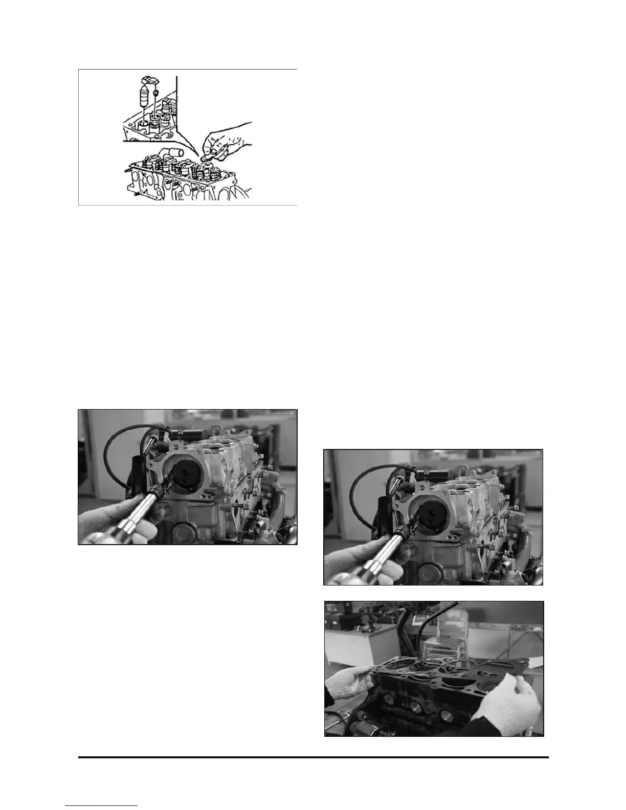
6. New cylinder head gasket to the cylinder block.
7. Cylinder head together with the exhaust and
intake manifolds, positioning them in the cylinder
block.
8. Valve lifters, pad and rocker arms.
9. Camshaft case with the camshaft assembled.
10. Camshaft and cylinder head new attaching bolts,
without tightening.