3.2 Analog Audio Out DB25-F Connector Pin-Out
The DB25-F connector for the analog audio output has the following pin-out (unbalanced
configuration only):
Pin # Signal Description Pin # Signal Description
1 Ch 8 plus 14 no connection
2 Ch 8 ground 15 Ch 7 plus
3 no connection 16 Ch 7 ground
4 Ch 6 plus 17 no connection
5 Ch 6 ground 18 Ch 5 plus
6 no connection 19 Ch 5 ground
7 Ch 4 plus 20 no connection
8 Ch 4 ground 21 Ch 3 plus
9 no connection 22 Ch 3 ground
10 Ch 2 plus 23 no connection
11 Ch 2 ground 24 Ch 1 plus
12 no connection 25 Ch 1 ground
13 no connection
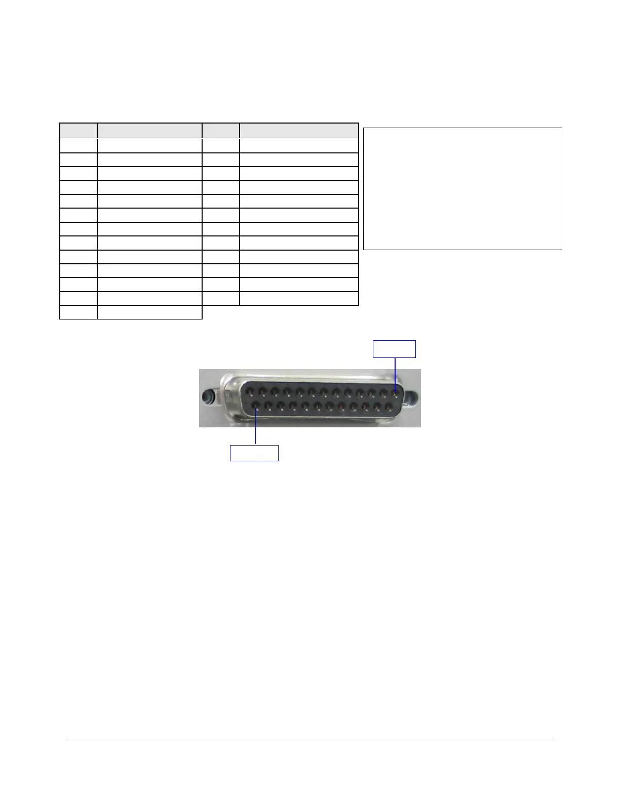
A picture of the DB25-F output connector is provided below:
Figure 4: AUD-D2A Analog Audio Output Connector (DB25-F)
D2K.OM.000181.DRM Page 9 Version 1.4
Doremi Cinema LLC
DCI Channel Map:
Channel 1: L (screen – left)
Channel 2: R (screen – right)
Channel 3: C (screen – center)
Channel 4: LFE (screen – low frequency
effects subwoofer)
Channel 5: Ls (surround – left wall)
Channel 6: Rs (surround – right wall)
Channel 7: Lc (screen – mid left to center)
Channel 8: Rc (screen – mid right to center)
Pin 1
Pin 25