2.2.4 Setting up Lock-In mode
Using a lock-in detection scheme, the Fiber Photometry Console can be used to detect fluorescence signals within strong
noise or separate multiple signals using a single detector
2
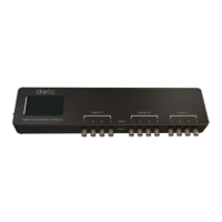
. An LED light source emits a sinusoidal signal at a given fre-
quency (called the Carrier), which is used as a reference. A detector is used to receive the resulting fluorescence. By
targeting the Carrier frequency of the reference signal (known as demodulation), the result is separated from ambient
noise at different frequencies. It is even possible to separate multiple carrier frequencies from a single signal.
Figure 2.9: Lock-in modulation timing diagram
Software Configuration
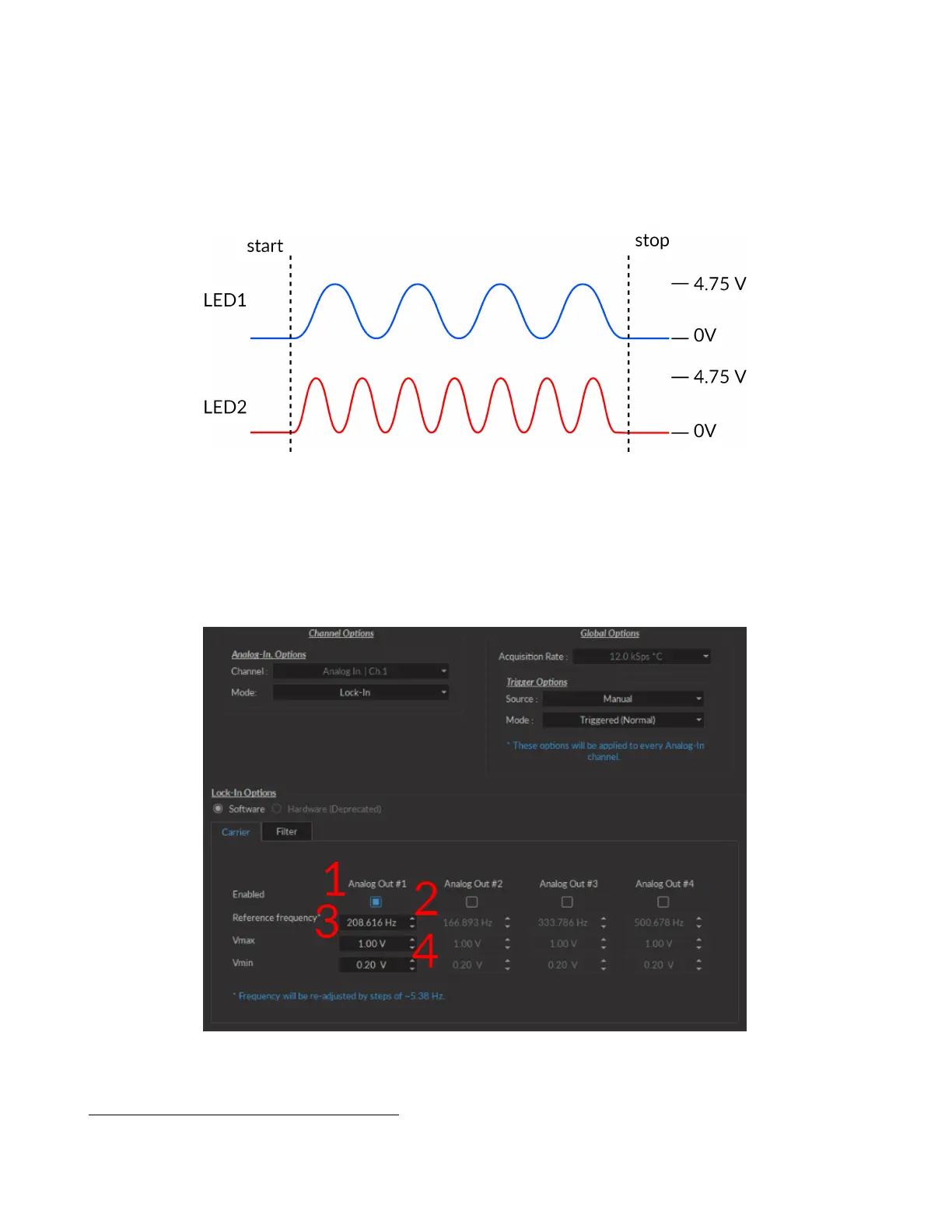
The following section describes the usage of the Lock-in mode for Analog Input channels. Once the Lock-in channel
mode is chosen, the Lock-in options box (Fig. 2.10) appears, containing the following parameters.
Figure 2.10: Channels configuration, Analog Input Lock-in Mode, Carrier Tab
2
Natural Neural Projection Dynamics Underlying Social Behavior Gunaydin LA, Grosenick L, Finkelstein JC, Kauvar IV*, Fenno LE, Adhikari A,
Lammel S, Mirzabekov JJ, Airan RD, Zalocusky KA, Tye KM, Anikeeva P, Malenka RC, Deisseroth K. Cell 157:15351551 (June 2014).
Chapter 2. Getting Started 22
 Loading...