1. The Channel List (Fig. 2.10) indicates which channels are used to output a reference frequency. Multiple output
channels can be selected for a single input channel. Any output channels already configured by a different input
channel will be usable, but not configurable. The output configuration must be changed in the initial input channel.
2. The Enabled checkboxes are used to select which output channels are in use.
3. The Reference frequency (Fig. 2.10) allows the choice of a reference frequency. The reference frequency should
not be a multiple a of known noise frequency (e.g. 60 Hz), or a multiple of another reference frequency.
4. The Vmax/Vmin (Fig. 2.10) defines the voltage sent from the console to the device. The minimum possible differ-
ence is of 0.1 V for the LEDD. The Vmin value is 0.1 V for the LEDD and 0.2 V for the LEDRV.
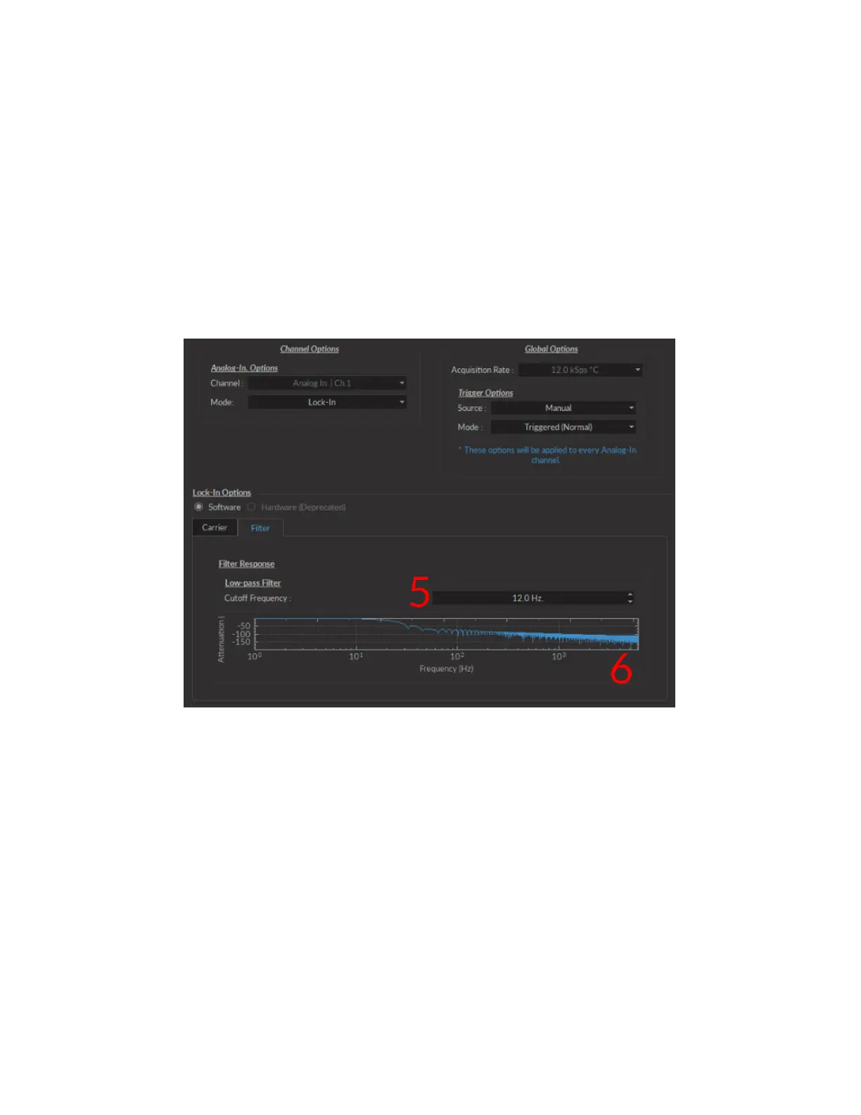
5. The Cutoff Frequency (Fig. 2.11) (the frequency at which a -3 dB attenuation will occur), found on the Filter tab
is kept fixed at 12 Hz for optimal filtering results.
6. The Filter response is displayed on the Filter tab.
Figure 2.11: Channels configuration, Analog Input Lock-in Mode, Filter Tab
Chapter 2. Getting Started 23