Do you have a question about the Dormakaba 701 and is the answer not in the manual?
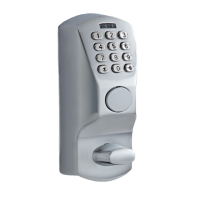
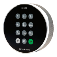
The dormakaba Keypad is a user interface designed for safe lock systems, available in both Display and non-Display variants. The Display variant provides on-screen messages, while the non-Display version relies on specific button combinations for various functions. This Keypad supports up to five safe locks simultaneously when used with the Multiplexer accessory.
The Keypad serves as the primary interface for controlling a safe lock system. It allows users to input commands and receive feedback (either visually on the Display variant or through button combinations on the non-Display variant) to operate the connected safe locks. The system is designed for secure access control to safes.
Mounting the Keypad involves several steps to ensure proper and secure attachment to the exterior of a safe door. First, holes must be drilled and tapped into the safe wall using a provided template, and the middle hole deburred. The Keypad base plate is then attached to the safe door using Phillips head screws, available in Metric M4-07 or US Customary Unit #8-32.
For deadbolt or springbolt installations, the safe lock cable is run through a cable holder and placed over the Keypad body posts. The spindle is pressed through the plastic housing, and the Keypad is placed on the door. It is then rotated 25 degrees clockwise to achieve vertical alignment. A crucial step involves measuring 0.354 inches (9.0 mm) past the safe door edge and marking the spindle for cutting. After removing the Keypad and spindle, the spindle is cut to the determined length, reinserted into the Keypad, and the cable is fed through the safe door opening. Finally, the Keypad is placed over the base plate grooves and rotated 25 degrees to its vertical position. It is critical not to use the anti-rotate device during this process for deadbolt/springbolt installations, as it will permanently lock the safe.
For swingbolt installations, the anti-rotate device is placed inside the four-hole locations in the housing and pressed down lightly until it sinks into the channel. The cable is run through the cable holder and over the Keypad body posts, and then through the safe door opening. The Keypad is placed over the base plate channel and rotated 25 degrees to the vertical position. Resistance will be felt as the anti-rotate device winds up. Once the anti-rotate device clicks into place, the Keypad is permanently locked in a vertical position and cannot be removed without damage. The swingbolt is then installed.
After physical installation, the Keypad and safe lock(s) are connected to form a system. For single lock systems: The cable from the Keypad is connected to the ENT port. If a Battery Box, Alarm Box, or AC power adapter is used, its cable is plugged into the safe lock's BAT port. Users then follow on-screen prompts for Display Entries or consult the Keypad Installation Guide (Document #7033.0320) for non-Display Entries to configure lock settings and initialization.
For multi-lock systems: The Keypad cable connects to the Multiplexer's side port. The first safe lock (Lock #1) connects from its ENT port to the #1 input on the Multiplexer. From Lock #1's BAT port, a connection is made to a power supply (either an AC Adapter or a Battery Box). This step is repeated for each additional safe lock. Display Entries will show on-screen prompts, while non-Display Entries require pound (#) commands. Further information can be found in the System User Guide (Document #7041.0320).
The Keypad Models 701, 702, 703, 704, and 705 (Input Units Keypads) are designed for use with High Security Lock Models:
The system can be powered by an AC adapter (Document #7037.0320), a Battery Box (Document #7035.0320), and/or battery power from the Keypad itself. Standard profile Keypads use a battery pack for primary power, while low-profile versions use a battery for backup in emergencies.
For standard profile Keypads:
For low profile Keypads:
This comprehensive guide ensures proper installation, connection, and maintenance of the dormakaba Keypad for secure safe operation.