1 About this manual
1.1 Information about the
manual
This instruction is part of the product. The instruction
comprises important instructions for safe operation.
Therefore, the instruction must be carefully read
before using the product. This instruction must be
kept during the service life of the product and must
be passed on with the product. This instruction
describes the installation, startup, maintenance and
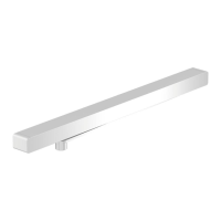
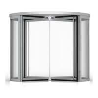
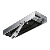
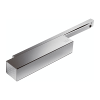
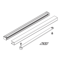
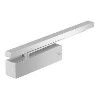
disassembly of the slide rail system GSR-EMR XEA.
The text of the instruction is supported by figures in a
separate figure part. The chapter numbers in the text
can be found again top left in the figures in the figure
part. There is not always a figure in the figure part to
support a chapter in the text.
1.2 Target groups
The installation, startup, maintenance and
disassembly must only be carried out by skilled staff
which has been authorized by dormakaba. The
acceptance test must only be carried out by skilled
staff that is certified for this by dormakaba. The
operation of the slide rail system may be carried out
by any person who is mentally and physically able.
1.3 Provided documents
• Installation manual
• Connection diagrams RMZ/RM-ED
• Data sheet about the use of arrest systems
• General building approval
1.4 Symbols and abbreviations
used
1.4.1 Safety instructions
DANGER
This signal word indicates a situation of
immediate risk, which will lead to death or
serious injury if not averted.
CAUTION
This signal word indicates a situation of
potential risk, which could lead to minor or
slight injury if not averted.
ATTENTION
This signal word indicates a situation of
potential risk, which could lead to damage
to property or the environment if not
averted.
TIPS AND RECOMMENDATIONS
This signal word indicates useful information
for efficient and trouble-free operation.
1.4.2 Further labeling
2.1. Step-by-step graphics
1 2 Position numbers of parts
The illustration shows the mounting
DIN-L on the hinge side.
Illustration shows mounting DIN-L on
the opposite hinge side.
The illustration shows the mounting
DIN-R on the hinge side.
Illustration shows mounting DIN-R on
the opposite hinge side.
1.4.3 Tool symbols
Allen wrench, e.g. wrench size 3
1.5 Glossary
EMF Electromechanical locking device
HT Manual release button
RMZ Smoke detection panel
RS Smoke switch
TS Door closer
2
G-EMR XEA
2018-11
dormakaba
WN 059420 45532
About this manualInstallation manual