The provided document is an installation manual for the "RTS Series Package 30" from dormakaba, specifically for an "Offset slide arm wood door and aluminum frame - hinges" application. This package appears to be a concealed overhead door closer system designed for integration into the door frame and the top of the door.
Function Description
The RTS Series Package 30 is a concealed overhead door closer system. Its primary function is to control the closing speed of a door, ensuring it closes smoothly and securely. The system is designed to be largely hidden from view, with the main closer mechanism installed within the header of the door frame and the slide arm and track integrated into the top edge of the door. This concealed design contributes to a clean aesthetic, making it suitable for applications where visible door closers might detract from the architectural design. The system utilizes an offset slide arm, which implies a specific geometry for its operation, likely to accommodate particular door and frame configurations or to optimize closing dynamics. The inclusion of a shock spring suggests a mechanism to absorb impact during door opening, preventing damage to the door or frame if the door is opened forcefully. The closer offers adjustable closing speeds, allowing customization to suit different door weights, traffic patterns, and safety requirements.
Important Technical Specifications
Based on the installation instructions, several technical specifications and components are highlighted:
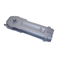
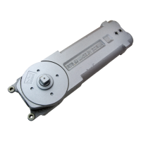
- Closer Mechanism: The core of the system, installed within the header. It contains the hydraulic or mechanical components responsible for controlling the door's closing motion.
- Mounting Bracket: Used to secure the closer into the side jamb of the door frame. Fastened with No. 8-32 pan head machine screws.
- Angle Bracket: Supports the closer within the header and connects it to the mounting bracket. Secured with 1/4-20 screws, lock washers, and nuts, as well as hex head machine screws and flat washers.
- Cover Plate: A decorative and protective element that slides into the frame, concealing the closer mechanism. Fastened with No. 8-32 flat head machine screws.
- Slide Arm: Connects the closer's spindle to the slide block within the track on the door. Secured to the spindle with a 1/4-20 socket head cap screw.
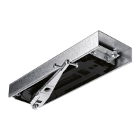
- Track: Installed on the top of the door, housing the slide block and shock spring assembly. Fastened with No. 8 flat head wood screws.
- Slide Block & Slide Block Pin: Components that move within the track, guided by the slide arm, to facilitate the door's closing action. The pin threads into the arm and is secured with a 3/16" hex wrench.
- Shock Spring Assembly: Integrated into the track, designed to absorb impact. It has settings for 90° and 105° deadstops, indicating the maximum opening angle at which the shock absorption is active or the door is stopped. Secured with a button head machine screw and 1/8" hex wrench.
- Fasteners: A variety of screws are specified, including:
- No. 8-32 pan head machine screws for the mounting bracket.
- No. 10-32 flat head machine screws for the header to mounting bracket.
- 1/4-20 flat head machine screws with lock washers and nuts for the header.
- Hex head machine screws and flat washers for the angle bracket to closer.
- Fillister head machine screws for mounting tabs on the closer.
- No. 8-32 flat head machine screws for the cover plate to mounting bracket.
- 1/4-20 socket head cap screw for the slide arm to spindle.
- Button head machine screw for the shock spring assembly to track.
- No. 8 flat head wood screws for the track to the door.
- Optional 8511 Applied Stop: An external stop mechanism that can be installed on the header. It requires No. 10-32 flat head machine screws for installation. Dimensions are provided for its cutout and mounting: 1-1/4" [32] height, 14-1/4" [362] length for the cutout, and overall dimensions of 17-1/2" [445] by 35" [889] for the stop itself, with a 1/8" [3] clearance.
Usage Features
- Concealed Design: The primary usage feature is its hidden installation, which maintains the aesthetic integrity of the door and frame.
- Adjustable Closing Speeds: The closer offers two independent valves for adjusting closing speeds:
- Valve "A": Controls the closing speed from the maximum opening angle down to 0°. Turning clockwise decreases the speed, while counter-clockwise increases it.
- Valve "B": Controls the closing speed from the maximum opening angle down to 20°. Turning clockwise decreases the speed, while counter-clockwise increases it. This allows for fine-tuning the door's behavior as it approaches the closed position, potentially preventing slamming.
- Shock Absorption: The integrated shock spring helps protect the door and frame from damage caused by forceful opening, extending the lifespan of the door assembly.
- Versatility: Designed for "Offset slide arm wood door and aluminum frame - hinges," indicating its suitability for specific door and frame types.
- Optional Applied Stop: The system can be complemented with an optional 8511 applied stop (or a stop by others), providing an additional layer of control over the door's opening range and preventing over-extension.
Maintenance Features
While the manual primarily focuses on installation and initial adjustments, some aspects imply maintenance considerations:
- Adjustable Valves: The presence of accessible adjustment valves for closing speeds suggests that these settings can be re-calibrated over time to compensate for wear, changes in environmental conditions, or evolving user preferences. This allows for ongoing optimization of the door's performance without requiring a full replacement.
- Secure Fastening: The detailed instructions for securely fastening all components (e.g., "TIGHTEN SECURELY!") are crucial for long-term stability and performance. Proper installation minimizes the need for frequent re-tightening or repairs.
- Concealed Components: While beneficial for aesthetics, the concealed nature of the closer might make routine inspection or more extensive maintenance tasks more involved, as access to the internal mechanisms requires removal of the cover plate and potentially other components. However, this also protects the components from external damage and dust, potentially reducing the frequency of maintenance.
- Durable Materials: The specification of various machine screws, lock washers, and robust components implies the use of durable materials designed for sustained operation in a door closer application, contributing to a longer service life and reduced maintenance needs.
- Template-Based Installation: The reliance on templates for preparing the header and door ensures precise component placement, which is fundamental for the closer to operate correctly and efficiently, thereby reducing the likelihood of premature wear or malfunction due to improper alignment.