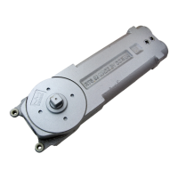
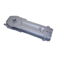
The RTS Series Package 29 is an installation kit for an offset slide arm wood door and frame, designed for use with hinges or pivots. This package provides the necessary components and instructions for installing a concealed overhead door closer, specifically the dormakaba RTS88 closer, into a wooden door and frame system.
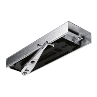
The primary function of this device is to control the closing speed and motion of a door, ensuring smooth and safe operation. It is particularly suited for applications where a concealed closer is desired for aesthetic reasons, as the main body of the closer is installed within the header of the door frame, and the arm mechanism is integrated into the top of the door.
Installation Process and Features:
The installation begins with preparing the header of the door frame and the top of the door according to provided templates. This involves routing out sections to accommodate the closer body, mounting bracket, and the track assembly.
-
Frame Preparation and Closer Installation:
- The mounting bracket is first secured to the closer using three No. 10 pan head wood screws.
- The closer is then inserted into the header by aligning its mounting tabs with the mounting bracket.
- An angle bracket is used to raise one end of the closer into its final position, and it is fastened to the closer with two hex head machine screws and flat washers.
- The angle bracket is then secured with two No. 12 pan head wood screws.
- Two fillister head machine screws are partially installed into the closer's mounting tabs, allowing for minor adjustments during installation.
- A cover plate is slid into the frame to conceal the closer body.
- The spindle end of the closer is fastened with two No. 8-32 flat head machine screws, and the opposite end is secured to the mounting bracket with two No. 6 flat head wood screws.
-
Door Preparation and Arm Assembly:
- The top of the door is prepared according to the template, which involves routing a channel for the track and shock spring assembly.
- The shock spring is assembled and then slid into the track. The end of the shock spring with a screw should face the 90° and 105° markings on the track.
- The shock spring assembly is aligned with either the 90° or 105° deadstop in the closer, depending on the desired opening angle.
- The shock spring assembly is secured to the track using a button head machine screw and a 1/8" hex wrench.
- A slide block pin is inserted through the slide block before the slide block is inserted into the track.
- The track is then fastened to the door with four No. 8 flat head wood screws.
- The slide arm is placed onto the closer's spindle and securely tightened with a 1/4-20 socket head cap screw.
- The door is positioned at approximately 45° of opening, and the arm is preloaded so that a hole in the arm aligns with the slide block pin.
- Finally, the slide block pin is threaded into the arm using a 3/16" hex wrench, and all connections are tightened securely.
Adjustments and Maintenance Features:
The RTS88 closer offers adjustable closing speeds, allowing for customization based on door weight, size, and user preference.
-
Adjusting Closing Speeds:
- Valve "A" controls the closing speed from the maximum opening angle down to 0°. Turning this valve clockwise decreases the closing speed, making the door close slower. Turning it counter-clockwise increases the closing speed, making the door close faster.
- Valve "B" controls the increased closing speed from the maximum opening angle down to 20°. Similar to Valve "A", turning it clockwise decreases the speed, and counter-clockwise increases it. These adjustments allow for fine-tuning the door's closing behavior, preventing slamming and ensuring a controlled closure.
-
Optional Applied Stop (8511):
- The package includes instructions for an optional 8511 applied stop, or allows for the use of other stops. This stop is installed on the header, above the door, to limit the door's opening angle and protect the door and surrounding structure from impact.
- The header needs to be prepared according to a specific template for the applied stop.
- The 8511 applied stop is then installed using three No. 10-32 flat head machine screws. This feature provides an additional layer of protection and control over the door's movement.
The design of the RTS Series Package 29 emphasizes concealed installation, which contributes to a cleaner aesthetic for the door and frame. The robust construction and adjustable features ensure long-term performance and adaptability to various door applications. While specific maintenance instructions beyond adjustments are not detailed in the provided excerpts, the use of durable materials and accessible adjustment valves suggests that routine checks and adjustments would be straightforward, contributing to the longevity and optimal function of the door closer system. The clear, step-by-step instructions and detailed diagrams facilitate a precise installation, which is crucial for the proper functioning and durability of the concealed closer.