Do you have a question about the Dormakaba 9000 Series and is the answer not in the manual?
Details wiring and operation for ED low energy operator with hardwired actuators and input device.
Wiring and operation for F9300 MLR exit device with PS610RF power supply and ES105 power transfer.
Guide to troubleshoot common issues with MLR units, covering latch retraction and operation problems.
Continues troubleshooting steps for MLR units, focusing on door preparation and alignment issues.
Further troubleshooting for MLR units, addressing touch bar and motor assembly adjustments.
Details the MLR specification label, including material, dimensions, and electrical requirements.
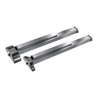
The dormakaba 9000 Series MLR (Motorized Latch Retraction) device is an advanced exit device designed to provide simultaneous electric latch retraction and dogging (depressed touch bar) for enhanced security and accessibility. This device is suitable for various door configurations and can be integrated into different access control systems.
The core function of the 9000 Series MLR is to allow for the electric retraction of the latch bolt, which can be triggered by an input device such as a card reader, keypad, or push button. This motorized retraction facilitates authorized entry and egress, making it ideal for high-traffic areas or applications requiring automated access. When the device is energized, the touch bar pulls in, retracting the latches, and holds them in this position as long as power is supplied. This feature enables hands-free operation and improves the flow of traffic through the door.
In a typical setup, the door is initially locked and secure. Authorized entrance is granted by presenting valid credentials at an exterior input device. This action triggers a low energy operator (if present) or the power supply to energize the MLR device, retracting the latch bolt. Depending on the configuration, this can also enable exterior wall actuators for automatic door opening or allow manual entrance via exterior trim. Egress is typically achieved by depressing an interior wall actuator or the touch bar of the exit device, which signals the operator to retract the latch bolt and open the door. Manual egress is always possible by depressing the touch bar, ensuring safety even in the event of power failure.
The device also supports "dogging," which means the touch bar can be depressed and held in the retracted position, allowing the door to remain unlocked and open without the need for continuous power or manual holding of the bar. This is particularly useful during peak hours or for temporary unrestricted access.
In the event of a loss of power, the MLR exit device is de-energized, causing the latch bolt to release and allowing for positive latching when the door closes. Immediate egress remains possible by depressing the touch bar, ensuring life safety compliance.
The 9000 Series MLR is designed for flexibility in installation and integration. It can be used in single door configurations with various components, including low energy operators, hard-wired actuators, and different power supply units. The device is compatible with dormakaba's ED Low Energy Operators and can be powered directly by them, simplifying wiring in some installations.
For access control, the MLR device integrates seamlessly with input devices such as card readers, keypads, and push buttons. The system can be configured to allow for different unlock times and manual override options. For instance, a key in the rim cylinder of an exterior pull trim can retract the latch bolt, bypassing the motorized retraction for manual authorized entry.
The device offers different sizes (A, B, C) to accommodate various door opening widths, with options for cutting to fit minimum door openings. This adaptability ensures that the MLR can be installed on a wide range of doors. Additional options like MS (Magnetic Switch), CD (Cylinder Dogging), LM (Latch Monitor), and BPA (Bolt Position Indicator) are available, further enhancing its functionality and integration capabilities.
The manual provides a comprehensive field troubleshooting guide to assist installers and maintenance personnel in diagnosing and resolving common issues. This guide emphasizes the importance of proper installation and adjustment to ensure optimal performance.
Key maintenance considerations include:
All corrections and changes should be performed with the input power removed to ensure safety. The troubleshooting guide is compiled from actual field installation issues, providing practical assistance to installers.
| Category | Door Opening System |
|---|---|
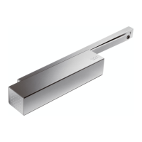
| Latching Speed | Adjustable |
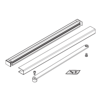
| Housing Material | Aluminum |
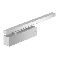
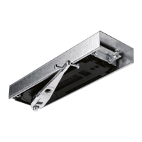
| Type | Door Closer |
| Opening Angle | Up to 180° (depending on installation) |
| Backcheck | Yes |
| Installation | Surface Mounted |
| Standards | EN 1154 |
| Series | 9000 Series |