dormakaba 9000 Series MLR Installation Instructions
95071186 01-2021Exit Device
3
Specifications
1 Installation
Specifications:
Electrical input requirements:
VDC + % filtered and regulated power supply; i.e. (DKPS-A). (PSUMLR- UK)
The unit may also be powered by the dormakaba operator.
Current: .A max, inrush, mA max. hold
Non polarized leads
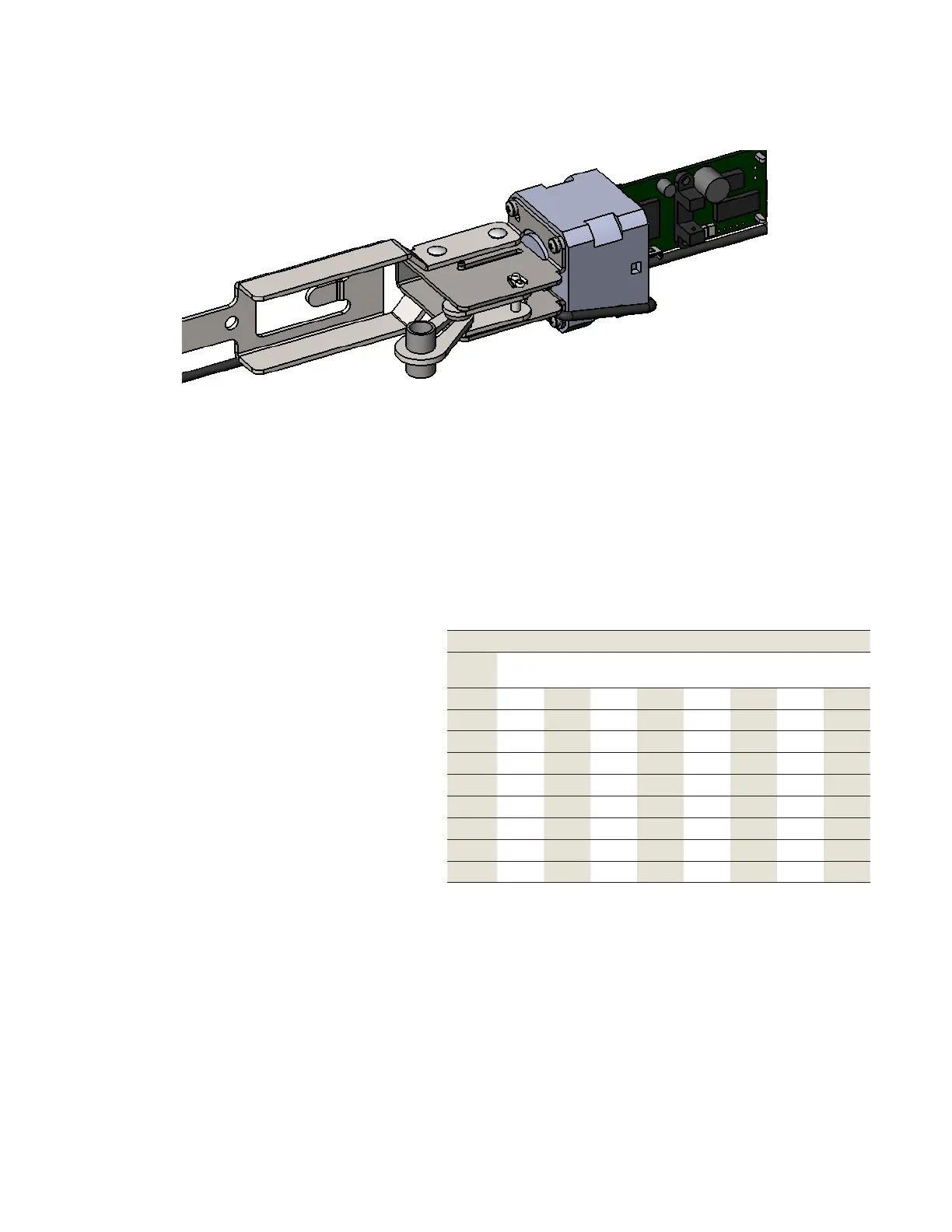
Provides simulatenous electric latch retraction and dogging (depressed touch bar)
Size A:
Fit : door opening without cutting
Can be cut to fit a : minimum door opening
Size B:
Fit : door opening without cutting
Can be cut to fit a : minimum door opening
Size C:
Fits : door opening without cutting
Using a shorter touch pad than the standard “B”
size allows it to be cut to ” door opening.
Additional options available such as MS, CD, LM, BPA, etc. However, minimum cut lengths may be different than
shown.
See additional pags for typical wiring diagrams. For additional diagrams or a custom project specific diagram
please contact dormakaba at number below.
Minimum Wire Guage Chart (AWG) for 24V AC/DC
Distance in Feet for 2 Conductors from Power Source to
Locking Device
AMPS 25 50 75 100 150 200 250 300
.25 18 18 18 18 18 18 18 18
.50 18 18 18 18 18 18 18 16
.75 18 18 18 18 18 16 16 14
1.00 18 18 18 18 16 16 14 14
1.50 18 18 18 16 16 14
2.00 18 18 16 16 14
2.50 18 18 16 14
3.00 18 16 14 14
 Loading...